The gas-to-liquids facility in Africa where I spent several years earlier in my career wasn’t an LNG plant — it converted natural gas to synthetic liquid fuels rather than liquefying the gas itself. But it shared the same cryogenic process control DNA that defines LNG operations.
We had refrigeration loops controlling temperatures down to -90°C, massive centrifugal compressors with tight anti-surge protection, heat exchangers that had to be brought down in temperature according to precise cool-down profiles to avoid thermal stress damage, and a control room that worked with the same Yokogawa CENTUM platform that runs most LNG plants worldwide.
That experience taught me what makes cryogenic process control different from anything else in the oil and gas industry. The temperatures are extreme — natural gas liquefies at -160°C, which is colder than anywhere on Earth’s surface. The materials science is unforgiving — carbon steel becomes brittle at LNG temperatures, requiring specialized aluminum and stainless steel construction throughout.
The energy intensity is enormous — refrigeration compressors driven by gas turbines of 60-130 MW each, with three to six compressors per liquefaction train. And the safety considerations are unique — cryogenic spills, vapor cloud formation, and rapid phase transitions create hazards that don’t exist anywhere else in process industries.
The DCS that runs an LNG plant must handle all of this. This guide is the practitioner explanation of DCS in LNG that I wish I’d had when I first encountered cryogenic process control. I’ll walk through the major units of an LNG facility, the critical control challenges, the Main Cryogenic Heat Exchanger (MCHE) as the heart of the plant, refrigerant compressor control, startup and shutdown sequences, and why Yokogawa CENTUM has dominated this industry segment.
If you’ve read our DCS in Refining guide, this article shows how the same DCS technology applies to a very different but equally demanding application domain — one that’s growing significantly as LNG becomes a primary global energy commodity.
TL;DR — Quick Answer: What Is DCS in LNG?
DCS in LNG refers to the application of Distributed Control Systems to liquefied natural gas plant operations — the continuous control of feed gas treatment (acid gas removal, dehydration, mercury removal, heavies removal), the cryogenic liquefaction process itself (propane precooling + mixed refrigerant circuits, Main Cryogenic Heat Exchanger), LNG storage and loading, and supporting utilities. LNG plants are among the most complex and safety-critical industrial facilities in the world.
The DCS in an LNG plant handles continuous control across all units at cryogenic temperatures down to -160°C, integrates with extensive safety instrumented systems (SIS), supports advanced process control (APC) for production optimization, manages massive refrigeration compressors with tight anti-surge protection, executes carefully sequenced startup and cool-down procedures, and connects to enterprise systems for cargo accounting and production reporting.
Yokogawa CENTUM VP is the dominant DCS platform in LNG with approximately 36% of installed liquefaction trains running CENTUM. Honeywell Experion PKS, Emerson DeltaV, and ABB 800xA also have significant LNG deployments. Modern LNG trains process 3-8 million tonnes per annum (MTPA) and deploy 15,000-30,000 I/O points across an integrated DCS.
Key concepts for LNG DCS:
- Cryogenic process control — operating temperatures down to -160°C
- Main Cryogenic Heat Exchanger (MCHE) — the critical equipment that defines plant performance
- Mixed refrigerant control — propane precool, mixed refrigerant (MR), or dual mixed refrigerant (DMR) circuits
- Refrigeration compressor anti-surge — 60-130 MW gas turbine driven compressors
- Startup cool-down sequencing — automated procedures to avoid thermal shock damage
- High SIS coverage — emergency shutdown, fire and gas detection, ESD valve management
- Cargo accounting integration — connection to Level 4 enterprise systems
What You Will Learn
This guide covers DCS in LNG at practitioner depth:
- Why LNG is one of the most specialized DCS application domains in the world
- The major units of an LNG plant and the specific DCS challenges of each
- The Main Cryogenic Heat Exchanger (MCHE) and its central role in plant control
- Refrigerant compressor control — propane precool, mixed refrigerant circuits
- Startup and cool-down sequencing for cryogenic equipment
- Safety considerations unique to LNG operations
- Vendor landscape and why Yokogawa CENTUM dominates LNG
- Advanced Process Control (APC) value capture in LNG
- Common LNG DCS implementation mistakes I’ve seen
Why DCS in LNG Is a Specialized Domain
LNG operations have characteristics that set them apart from other process industries and that drive specialized DCS requirements.
DCS in LNG cryogenic operating temperatures.
Natural gas liquefies at approximately -160°C (-260°F) at atmospheric pressure. This temperature is colder than anywhere on Earth’s surface. Materials behave differently at these temperatures — carbon steel becomes brittle and unsuitable, requiring 9% nickel steel, aluminum, or stainless steel throughout the cold sections. Thermal expansion and contraction during cool-down and warm-up create stresses that can damage equipment if not managed carefully.
The DCS must measure temperatures across an extreme range — from ambient conditions in the early process stages down to -160°C in the cold box. Temperature sensors at cryogenic conditions require specialized RTDs with extended calibration ranges, and the control logic must handle this temperature span without losing precision.
DCS in LNG massive energy intensity.
LNG liquefaction is energy-intensive. A modern 5-MTPA liquefaction train typically consumes 80-150 MW of compression power, driven by industrial gas turbines (GE Frame 7 or 9, Siemens SGT-700, Mitsubishi M501) rated at 30-130 MW each. These compressors are among the largest rotating equipment in any industrial process.
The DCS controls these compressors continuously, with anti-surge protection, capacity control, performance optimization, and integration with the gas turbine driver controls. A single compressor trip can shut down the entire liquefaction train.
Production scale and economics.
A modern LNG train produces 3-8 MTPA. At LNG prices of $10-20 per MMBtu, a single train generates $1-3 billion in revenue annually. A 1% production improvement is worth $10-30 million per year. The DCS, integrated with advanced process control, is what captures this economic value through optimized operation.
DCS in LNG safety criticality.
LNG creates unique safety hazards. Cryogenic spills can form dense vapor clouds that travel along ground level before warming and dispersing. Rapid phase transition (RPT) events when LNG contacts water can create destructive overpressure waves. Material embrittlement from cryogenic exposure can cause sudden brittle fracture. The 1944 Cleveland LNG fire and the 1973 Staten Island LNG accident remain reference incidents driving LNG safety design.
The SIS in an LNG plant handles thousands of safety functions across feed gas reception, liquefaction, storage, and loading. For broader SIS context, see our Safety Instrumented System guide.
Continuous operation expectation.
Like refining, LNG operations run continuously between scheduled turnarounds. Unlike refining, LNG facilities typically have only 1-3 liquefaction trains, so losing one train means losing 30-100% of plant production. Reliability requirements drive DCS architecture choices — redundancy, SIL 3 protection, and lifecycle support all matter intensely.
For broader DCS context, see our What Is a DCS cornerstone guide.
The Major Units of an LNG Plant and Their DCS in LNG Challenges
DCS in LNG covers every major unit of the plant. Every LNG plant has its own configuration, but most include a similar set of unit operations. Each unit has specific DCS challenges. Here’s the practical walkthrough.
Feed Gas Reception and Metering.
Feed gas enters the plant from upstream pipelines or gas processing facilities. Initial operations include pressure reduction, metering for custody transfer (often subject to regulatory measurement requirements), and feed gas analysis. Composition monitoring is critical because downstream liquefaction performance depends on knowing exactly what’s in the feed.
DCS challenges:
- Custody transfer metering — high-accuracy flow measurement and totalization for commercial accounting
- Composition monitoring — gas chromatography integration; results affect downstream control
- Feed gas conditioning — pressure and temperature control to downstream specifications
Feed gas reception typically adds 1,000-2,000 I/O.
Acid Gas Removal (AGR / Amine Treating).
Natural gas contains hydrogen sulfide (H₂S) and carbon dioxide (CO₂) that must be removed before liquefaction. CO₂ freezes at LNG temperatures and would plug the MCHE; H₂S is toxic and corrosive. Amine absorption columns (typically MDEA or activated MDEA) remove both contaminants.
DCS challenges in AGR:
- Amine circulation control — flow rate to absorber based on feed gas composition
- Lean amine concentration control — water balance in the amine regenerator
- Absorber temperature profile — affects absorption efficiency
- Acid gas treatment — sulfur recovery unit (SRU) handling H₂S
AGR typically adds 2,000-3,500 I/O.
Dehydration.
After amine treating, the gas is saturated with water from the amine system. Water must be removed below LNG-friendly levels (typically <1 ppm) to prevent ice formation in the cryogenic exchangers. Molecular sieve dryers operate in cycles — adsorption phase, regeneration phase, cooling phase.
DCS challenges in dehydration:
- Dryer sequencing — typically 3-4 dryer beds cycling between phases
- Regeneration gas temperature control — heating regenerated dryer beds to drive off water
- Moisture analyzer integration — confirming dryer effluent meets specification
Dehydration typically adds 1,500-2,500 I/O.
Mercury Removal.
Even trace mercury in feed gas causes catastrophic corrosion of aluminum components in the MCHE — aluminum and mercury form amalgams that destroy aluminum metallurgy. Mercury removal beds (typically sulfur-impregnated activated carbon or non-regenerative beds) protect downstream equipment.
DCS challenges in mercury removal:
- Bed performance monitoring — pressure drop, breakthrough indication
- Bed changeout coordination — beds are changed periodically rather than regenerated
Mercury removal adds 500-1,000 I/O.
Heavies Removal.
Heavier hydrocarbons (C₅+ components, benzene, aromatics) freeze at LNG temperatures and must be removed before liquefaction. Different technologies handle this — distillation, scrub columns, or NGL recovery integration.
DCS challenges in heavies removal:
- Distillation column control — typical column tray temperature profile and pressure control
- NGL product handling — interfaces with NGL recovery if integrated
- Bottoms quality monitoring — preventing heavies carryover to liquefaction
Heavies removal typically adds 1,500-2,500 I/O.
Liquefaction — The Heart of the Plant.
The liquefaction section is where LNG is actually made. Modern technologies include propane precooled mixed refrigerant (C3MR — most common), dual mixed refrigerant (DMR), and other variations. The propane precool circuit cools the feed gas from ambient to approximately -35°C. The mixed refrigerant circuit (containing methane, ethane, propane, and nitrogen in carefully optimized proportions) further cools the gas to -160°C in the MCHE.
DCS challenges in liquefaction:
- MCHE temperature profile control — cool-down rate, cold-end approach, sub-cooling
- Mixed refrigerant composition control — make-up rates for methane, ethane, propane, nitrogen
- Propane refrigeration loop control — propane compressor performance, evaporator levels
- Compressor capacity coordination — propane and MR compressors must work together
- Anti-surge protection on all major refrigeration compressors
- Heat exchanger approach temperatures — direct indicator of efficiency and capacity
Liquefaction is the most complex single section and typically dedicates 4,000-7,000 I/O.
LNG Storage and Loading.
LNG storage tanks are massive (typically 160,000 m³ to 250,000 m³) double-containment cryogenic tanks. Loading systems transfer LNG to ships through cryogenic marine loading arms.
DCS challenges in storage and loading:
- Tank level and temperature monitoring — critical for safety and inventory management
- Boil-off gas (BOG) management — natural evaporation from tanks; BOG compressors return it to the process or to fuel gas
- Loading arm sequencing — cool-down, loading, drainage, warm-up procedures
- Ship-shore link — ESD coordination between LNG plant and receiving vessel
Storage and loading typically adds 1,500-3,000 I/O.
Utilities and Offsites.
LNG facilities require massive utility systems — power generation (often integrated from gas turbine drivers), seawater cooling (or air cooling for inland plants), instrument air, nitrogen for blanketing, flare systems for relief and during startup, and extensive fuel gas and tail gas management.
Utilities add 5,000-10,000 I/O depending on plant configuration.
The MCHE — The Critical Equipment for DCS in LNG
The MCHE is the equipment that defines LNG plant performance. Most modern LNG plants use spiral-wound exchangers (Air Products SWHE) or plate-fin (brazed aluminum) exchangers, with the choice driven by liquefaction technology selection.
Why the MCHE matters so much for DCS in LNG.
The MCHE is where the actual liquefaction happens — natural gas enters at approximately -35°C and exits at -160°C as LNG. The exchanger contains hundreds of kilometers of tube bundles in a single vessel that may be 5 meters in diameter and 40 meters tall. It cannot be easily inspected, repaired, or replaced. Damage typically means a multi-week shutdown to repair and a many-month financial impact.
DCS in LNG control of the MCHE.
The MCHE doesn’t have many direct manipulated variables — there’s no “MCHE valve” the operator adjusts. Instead, MCHE behavior is controlled indirectly through:
- Refrigerant composition — adjusted slowly over time as feed changes
- Refrigerant flow rates — propane and MR compressor capacities
- Cold-end approach temperature — the temperature difference between exiting LNG and entering MR; controlled by MR composition and flow
- Sub-cooling — final temperature of LNG product
The DCS continuously calculates and displays these key MCHE indicators, and operators adjust upstream variables to maintain MCHE performance within targets.
Cool-down and warm-up sequences.
The most challenging DCS operation involving the MCHE is the cool-down sequence during startup. The MCHE must be brought from ambient temperature down to -160°C following a carefully controlled temperature profile. Too fast and thermal stress damages the equipment; too slow and startup takes longer than necessary. Yokogawa pioneered “Modular Procedural Automation” (MPA) for automated cool-down sequencing, significantly reducing startup time.
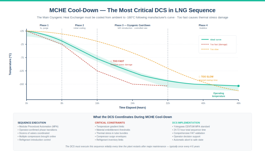
A typical cool-down sequence:
- Pre-cooling with nitrogen circulation
- Gradual introduction of cold mixed refrigerant
- Controlled temperature decrease following equipment manufacturer’s curve
- Eventual stabilization at operating conditions
The entire sequence takes 24-72 hours depending on plant size and prior thermal state. During this time, the DCS must coordinate dozens of valves, multiple compressors, and the entire refrigerant system following the cool-down profile.
Refrigerant Compressor Control in DCS in LNG
The refrigeration compressors are the largest pieces of rotating equipment in an LNG plant. Typically:
- Propane compressor — 30-50 MW driver, three to four compression stages
- Mixed refrigerant compressor — 50-130 MW driver, two to three compression stages
- For DMR plants, separate warm and cold refrigerant compressors
These compressors run continuously at design conditions and must be protected against operational hazards.
Anti-surge protection.
Centrifugal compressors have a surge limit below which forward flow stops and reverse flow occurs in pulses. Surge causes severe mechanical damage and can destroy the compressor in seconds if not prevented. Every refrigeration compressor in an LNG plant has dedicated anti-surge control implemented through:
- Surge controller — calculates current operating point relative to surge limit
- Recycle valve — opens to recirculate flow when approaching surge
- Coordination with main control loops — capacity reduction during low-demand periods
Modern LNG plants often use specialized anti-surge controllers (CCC Series 5, Tri-Sen, vendor-native) that interface with the DCS through high-speed digital communication. Anti-surge control performance directly affects plant uptime.
Compressor capacity control.
Refrigeration demand varies with feed gas rate, feed composition, ambient temperature, and production targets. Compressors must adjust capacity to match demand through:
- IGV (Inlet Guide Vane) control — primary capacity control mechanism
- Variable speed drives — for some installations, especially electric motor-driven
- Gas turbine speed control — for turbine-driven compressors, coordinating with turbine governor
The DCS coordinates all of these through master controllers that maintain target refrigeration conditions while staying within compressor operating envelopes.
Coordination between compressors.
In a C3MR plant, propane and MR compressors must work together. If propane circuit isn’t providing enough precooling, MR circuit can’t reach target temperatures. The DCS coordinates capacity between compressors, often through MPC (advanced process control) optimization layers above the basic DCS control.
DCS in LNG Startup and Shutdown Sequences
LNG plant startup and shutdown sequences are among the most complex automated procedures in any process industry. They involve coordinating dozens of major equipment items, hundreds of valves, and complex interlocks across multiple hours.
Cool-down sequence (startup).
After major maintenance or extended shutdown, the plant must be cooled from ambient temperatures to operating temperatures. Key steps:
- Inert gas purge — replace air with nitrogen throughout cold equipment
- Initial cooling — circulate cold gas through equipment at controlled rates
- Refrigerant introduction — gradually introduce mixed refrigerant
- MCHE cool-down — follow manufacturer’s temperature curve
- Compressor startup — bring compressors online in sequence
- Production stabilization — reach operating conditions
The DCS sequences this process through automated procedures with operator-confirmed step transitions. Modern plants use Modular Procedural Automation (MPA) to reduce startup time from days to hours where possible.
Warm-up sequence (shutdown).
The reverse process — bringing the plant from operating temperatures back to ambient for inspection or maintenance. Must be controlled to avoid thermal stress damage. Typically takes 2-5 days for major equipment.
Emergency shutdown.
When safety conditions require immediate plant shutdown, the SIS executes coordinated emergency shutdown across all units. The DCS supports this through alarm management, operator interface, and post-trip recovery procedures.
Safety Considerations Unique to LNG
DCS in LNG must handle safety hazards unique to cryogenic operations. LNG operations face safety hazards that don’t exist in other process industries. The SIS handles these systematically.
Cryogenic spill containment.
LNG spills produce vapor clouds that travel along ground level (the cold vapor is denser than air initially). Spill containment systems (impounding basins, drainage to safe areas, water curtains) protect personnel and equipment. The DCS monitors spill detection sensors and triggers protective actions.
Vapor cloud detection.
Gas detectors throughout the plant detect methane vapor clouds before they reach ignition sources. Detection triggers emergency shutdown of nearby equipment and warning of operators. Modern plants use both point detectors and area open-path detectors.
Rapid Phase Transition (RPT).
If LNG contacts water (typically during marine loading), rapid phase transition can occur — the LNG instantaneously vaporizes with explosive overpressure. RPT is mitigated through procedure design (avoiding LNG-water contact) and through automated loading sequences that prevent the conditions causing RPT.
Fire and gas detection.
LNG plants have extensive fire and gas detection — flame detectors at process equipment, gas detectors throughout cold sections, manual call points, and heat detectors. The fire and gas system is typically SIL 2 or higher and triggers automated emergency response including isolation valves, deluge systems, and personnel alerts.
Cryogenic embrittlement.
Materials at LNG temperatures behave differently than at ambient. The DCS monitors temperature in piping and equipment, alerting operators if material temperatures approach embrittlement thresholds. Cool-down procedures explicitly manage temperatures to avoid brittle fracture conditions.
For comprehensive SIS context including LNG-specific applications, see our Safety Instrumented System guide.
Vendor Landscape — Why Yokogawa CENTUM Dominates LNG
Among platforms used for DCS in LNG, Yokogawa CENTUM VP has approximately 36% of liquefaction trains installed globally — a substantial dominant position. The other major platforms (Honeywell Experion PKS, Emerson DeltaV, ABB 800xA) all have significant LNG installations but smaller market share specifically in liquefaction.
Why Yokogawa CENTUM has dominated LNG.
Several factors contributed to Yokogawa’s LNG market position:
- Early Japanese LNG market presence — Japan was an early LNG import market, and Yokogawa had strong domestic Japanese presence in process control. Early LNG export plants supplying Japan often standardized on Yokogawa.
- Distributed database architecture — CENTUM’s FCS-based distributed database handles LNG scale and reliability requirements well
- Determinism through proprietary OS — the FCS proprietary real-time OS provides the predictable execution that cryogenic process control requires
- Reference experience compounding — once Yokogawa had multiple LNG references, new LNG projects often preferred a vendor with proven experience
- Modular Procedural Automation (MPA) — Yokogawa’s automated startup sequencing technology became widely adopted in LNG
- ProSafe-RS SIS native integration — tight integration with CENTUM for the extensive safety systems LNG requires
For broader CENTUM context, see our Yokogawa CENTUM VP architecture guide.
Honeywell Experion PKS in LNG.
Honeywell has significant LNG presence, particularly in projects led by US-based or European EPC contractors. Experion + Safety Manager combinations are used in multiple major LNG plants. Honeywell’s strength in oil and gas mega-projects translates to LNG.
For broader Experion context, see our Honeywell Experion PKS architecture guide.
Emerson DeltaV in LNG.
DeltaV is less common in mainline LNG liquefaction than CENTUM or Experion but has growing presence in LNG receiving terminals and smaller-scale LNG facilities. CHARMs I/O technology has appeal for projects with late-stage signal type changes.
For broader DeltaV context, see our Emerson DeltaV architecture guide.
ABB 800xA in LNG.
ABB has LNG deployments, particularly in projects where ABB also supplies electrical and instrumentation as integrated packages. 800xA’s strength in electrical integration appeals to LNG projects with large electrical infrastructure.
Advanced Process Control in LNG
DCS in LNG integrates closely with Advanced Process Control. LNG plants are prime candidates for Advanced Process Control (APC) because of the high economic value of small efficiency improvements at LNG scale.
Typical APC applications in LNG:
- Mixed refrigerant composition optimization — adjusting MR composition to match feed gas variations
- Compressor coordination — optimizing capacity sharing between propane and MR compressors
- MCHE approach temperature optimization — pushing toward minimum approach without thermal violations
- Production maximization vs energy efficiency — economic trade-off optimization
- Multi-train coordination — for facilities with multiple trains, optimizing shared utilities
APC value capture.
Well-tuned APC in an LNG plant typically captures 1-3% production improvement or equivalent energy savings. On a 5-MTPA train at $12/MMBtu LNG, that’s $25-75 million annually. The APC investment pays back in months.
Major APC vendors active in LNG include AspenTech DMC3, Honeywell Profit Suite, Yokogawa Robust MPC, and Emerson PredictPro. For broader DCS-APC integration context, see our PID Tuning Methods guide.
Common LNG DCS Mistakes I’ve Seen
After working on oil and gas EPC projects with gas processing and cryogenic operations, here are the recurring mistakes I see in DCS in LNG work:
Underestimating cool-down sequence engineering. Cool-down procedures are not just operator scripts — they’re automated sequences that must coordinate dozens of equipment items over many hours. Treating cool-down as an operations concern rather than a DCS engineering concern leads to procedures that don’t work cleanly when actually used.
Inadequate anti-surge engineering. Refrigeration compressor anti-surge protection is critical to LNG plant reliability. Underspecified anti-surge controllers, slow recycle valves, or poor integration between anti-surge and main control loops cause compressor trips and unplanned shutdowns.
Treating utilities as second-class systems. Gas turbines, seawater systems, nitrogen generation, instrument air — these aren’t glamorous but they’re essential to LNG operation. A utility trip can cause a liquefaction train shutdown. DCS quality for utilities must match the liquefaction system.
Skipping HMI rationalization for cryogenic equipment. Operators monitoring -160°C process equipment need exceptional situational awareness. ISA-101 HMI design is even more important in LNG than in ambient-temperature processes because operators don’t have intuitive feel for cryogenic conditions the way they do for things they can sense.
Inadequate alarm management. LNG plants have many alarms — feed gas, AGR, dehydration, liquefaction, storage, loading, utilities. Without ISA-18.2 rationalization, operator effectiveness suffers, particularly during abnormal situations.
Treating SIS as DCS afterthought. DCS in LNG SIS work is its own engineering discipline with extensive cause-and-effect matrices, multiple shutdown systems, fire and gas integration, and ship-shore ESD coordination. Folding SIS into DCS commissioning creates problems that emerge during operations.
Underspecified vibration monitoring on compressors. Refrigeration compressors are critical equipment. Vibration monitoring isn’t just maintenance information — it’s online protection that interfaces with DCS for early warning before bearing or rotor damage.
Ignoring cargo accounting integration. LNG is sold in cargoes; accounting accuracy matters financially. Integration between the DCS, custody transfer metering, and cargo accounting systems must work correctly from commissioning. Mistakes here cause commercial disputes.
Mismatched cybersecurity zones. LNG plants are critical infrastructure. IEC 62443 zones and conduits need careful definition from project inception. Add-on cybersecurity after the fact creates compliance gaps and operational vulnerabilities.
Insufficient FAT for cool-down procedures. Cool-down sequences are difficult to test on real equipment. Comprehensive Factory Acceptance Testing using simulators is essential to verify sequence logic before commissioning.
Underestimating DCS in LNG operator training. Operating an LNG plant requires deep cryogenic process understanding that operators from other industries don’t have. Training programs and DCS interfaces must support knowledge transfer effectively.
Frequently Asked Questions
What is DCS in LNG?
DCS in LNG refers to the application of Distributed Control Systems to liquefied natural gas plant operations — continuous control of feed gas treatment, cryogenic liquefaction, LNG storage and loading, and utilities at temperatures down to -160°C. Modern LNG trains process 3-8 million tonnes per annum and deploy 15,000-30,000 I/O points on integrated DCS platforms.
Which DCS platform is most common in LNG?
Yokogawa CENTUM VP has approximately 36% of LNG liquefaction trains globally — the dominant position. Honeywell Experion PKS, Emerson DeltaV, and ABB 800xA also have significant LNG installations but smaller market share specifically in liquefaction. CENTUM’s dominance comes from early Japanese market presence, distributed database architecture suited to LNG scale, and accumulated reference experience.
What is the MCHE in an LNG plant?
The Main Cryogenic Heat Exchanger (MCHE) is the equipment where natural gas is actually liquefied — cooled from approximately -35°C entering to -160°C exiting as LNG. The MCHE is typically a spiral-wound exchanger (Air Products SWHE) or brazed aluminum plate-fin exchanger, 5 meters in diameter and 40 meters tall, containing hundreds of kilometers of tube bundles. It defines plant performance and cannot be easily repaired if damaged.
What is C3MR liquefaction?
C3MR (Propane Precooled Mixed Refrigerant) is the most common LNG liquefaction technology. Feed gas is first cooled to approximately -35°C using a propane refrigeration loop, then further cooled to -160°C in the MCHE using a mixed refrigerant (typically containing methane, ethane, propane, and nitrogen). C3MR was originally developed by Air Products and remains the dominant LNG technology globally.
How big are LNG refrigeration compressors?
Modern LNG refrigeration compressors are among the largest rotating equipment in process industries. Propane compressors typically have 30-50 MW drivers; mixed refrigerant compressors typically have 50-130 MW drivers. Most are driven by industrial gas turbines (GE Frame 7 or 9, Siemens SGT-700, Mitsubishi M501), with anti-surge control critical to operation.
What is the LNG plant cool-down sequence?
Cool-down brings the plant from ambient temperatures to operating temperatures (-160°C in the MCHE) through a carefully controlled sequence taking 24-72 hours. The DCS coordinates inert gas purging, gradual cold gas introduction, refrigerant introduction, MCHE cool-down per manufacturer’s curve, and compressor startup. Modern plants use Modular Procedural Automation (MPA) to reduce cool-down time.
What safety systems are unique to LNG?
LNG faces unique safety hazards including cryogenic spills with vapor cloud formation, rapid phase transition (RPT) when LNG contacts water, cryogenic embrittlement of materials, and methane vapor ignition. SIS coverage in LNG includes extensive fire and gas detection, cryogenic spill containment, emergency shutdown systems, ship-shore ESD coordination, and fire suppression.
How much I/O does an LNG plant DCS have?
A modern LNG plant with one liquefaction train typically deploys 15,000-25,000 I/O. Plants with multiple trains scale accordingly. Largest LNG facilities (Qatar’s North Field expansion, Gorgon, RasGas) exceed 50,000 I/O across their integrated control systems.
What is APC in LNG?
Advanced Process Control (APC) in LNG includes multivariable predictive control (MPC) for mixed refrigerant composition optimization, compressor coordination, MCHE approach temperature management, and production vs energy trade-off optimization. APC typically captures 1-3% production improvement or energy savings — $25-75 million annually on a 5-MTPA train.
How does LNG DCS compare to refinery DCS?
Both apply the same DCS technology to continuous, safety-critical, large-scale processes. Refining has more diverse unit operations (CDU, VDU, FCC, hydrocracker, reformer, etc.) and larger I/O counts (20,000-100,000 vs 15,000-30,000 for LNG). LNG has more specialized cryogenic challenges, more concentrated compressor power, and unique cool-down sequencing requirements. For refining context, see our DCS in Refining guide.
Conclusion
LNG operations represent one of the most specialized and demanding domains for distributed control systems in the world. The combination of cryogenic temperatures (-160°C), massive refrigeration compressor power (60-130 MW each), production-critical equipment that can’t be easily repaired (the MCHE), and unique safety hazards (cryogenic spills, vapor clouds, rapid phase transition) creates engineering requirements that few other industries match.
The most important practical truths about DCS in LNG:
- DCS in LNG drives specialized engineering across cryogenic process control, refrigeration compressor management, and automated cool-down sequencing
- The Main Cryogenic Heat Exchanger (MCHE) is the equipment that defines plant performance and cannot be easily replaced
- Refrigerant compressor anti-surge protection is critical to plant reliability — compressor trips shut down the train
- Cool-down and warm-up sequences require automated procedures coordinating dozens of equipment items over many hours
- Yokogawa CENTUM dominates LNG with approximately 36% market share, though Honeywell, Emerson, and ABB also have significant LNG presence
- Advanced Process Control captures 1-3% production improvement worth tens of millions of dollars annually per train
- LNG safety systems handle hazards unique to cryogenic operations — spill containment, vapor cloud detection, rapid phase transition prevention
On the gas-to-liquids facility where I worked earlier in my career, the cryogenic process control challenges were directly analogous to DCS in LNG operations even though the products were different. The same Yokogawa CENTUM platform that dominates LNG ran our refrigeration loops, anti-surge controllers, and cool-down sequences. The lessons learned about cryogenic process control discipline transfer directly between gas-to-liquids, LNG, and other deep-cryogenic operations.
If you’re approaching an LNG project, resist the temptation to treat it as just another oil and gas process plant. The cryogenic requirements, the equipment criticality, the safety considerations, and the production-cost ratio all create unique engineering challenges. Plan for them explicitly.
Engage operations early — operating an LNG plant requires deep specialized knowledge that takes years to develop. And recognize that LNG DCS work is genuinely specialized engineering that deserves vendor partnerships, training investment, and lifecycle discipline matching the scale of LNG facility investment.
For broader DCS context, see our What Is a DCS cornerstone guide. For platform-specific implementation, see our Yokogawa CENTUM VP architecture guide (the dominant LNG platform), Honeywell Experion PKS architecture guide, and Emerson DeltaV architecture guide.
For control theory underlying LNG critical loops, see our PID Tuning Methods guide, Cascade Control guide, Feedforward Control guide, and Ratio Control guide.
For safety and standards context, see our Safety Instrumented System guide, ISA-101 HMI Design guide, ISA-18.2 Alarm Management guide, and ISA-95 Enterprise Integration guide.
For the sibling application in petroleum refining, see our DCS in Refining guide.
About the Author
Daniel Reed is an Instrument and Controls Engineer with 14+ years of oil and gas EPC experience across onshore and offshore projects in Asia and Africa. He currently works as a client-side I&C completion engineer on a large oil and gas mega-project in Asia, where he has been involved with Honeywell Experion PKS and Safety Manager since 2018.
His earlier work covered Yokogawa CENTUM and Triconex SIS on an offshore brownfield in Africa (2015-2018), and Yokogawa CENTUM and ProSafe-RS on a gas-to-liquids facility in Africa with cryogenic process control directly analogous to LNG operations. His focus is engineering deliverable review, control and safety system commissioning, HAZOP/SIL/SIF participation, FAT/SAT execution, and vendor coordination across Honeywell, Yokogawa, Triconex, Allen-Bradley, and Siemens platforms.