The first cascade control loop I commissioned was a furnace outlet temperature controller on a gas-to-liquids facility in Africa. The fuel gas pressure to the burners was fluctuating because of upstream changes on a shared header, and the simple feedback PID we’d commissioned was constantly chasing the disturbance. Operations was complaining about temperature swings of ±5°C on a process that needed ±1°C.
The senior engineer on the project walked over, looked at the trends for ten minutes, and said: “Add a fuel gas flow loop as the secondary — cascade configuration.” Within a day the temperature was holding within ±0.5°C, the operators stopped calling, and I’d learned what cascade actually does in practice.
Cascade control is one of the most powerful advanced control techniques available in modern DCS platforms. It’s also one of the most misunderstood. Many engineers throw cascade at problems where simple feedback would work fine. Other engineers avoid cascade because they don’t understand how to tune it. The textbooks explain the theory but rarely the practical realities — bumpless transfer, mode transitions, the tuning sequence, vendor-specific implementation quirks.
This guide walks through cascade control from a working DCS commissioning engineer’s perspective. I’ll cover what cascade is, when it’s the right answer (and when it isn’t), how the primary and secondary loops actually work together, the correct tuning sequence, real examples from oil and gas projects, and the configuration mistakes that show up routinely on real plants.
If you’ve read our PID Tuning Methods guide, this article builds directly on those concepts. Cascade control is fundamentally PID control applied in a specific architectural configuration.
TL;DR — Quick Answer: What Is Cascade Control?
Cascade control is an advanced control architecture where two PID controllers are arranged in series. The output of an outer (primary or master) controller becomes the setpoint of an inner (secondary or slave) controller, which then drives the final control element. The primary controller manages the slow, important process variable (typically temperature, level, or composition); the secondary controller manages a fast intermediate variable (typically flow, pressure, or position).
The benefit is faster disturbance rejection on the secondary variable before it propagates to the primary variable. A pressure fluctuation in a fuel gas header gets corrected by the secondary fuel gas flow controller in seconds, before it can affect the slower furnace outlet temperature controlled by the primary loop.
It’s the most widely used advanced control architecture in process industries. It’s found in essentially every refinery, gas plant, petrochemical facility, and power station. Implementation in modern DCS platforms — Honeywell Experion PKS, Yokogawa CENTUM VP, Emerson DeltaV — is straightforward through standard function blocks. The discipline comes in tuning, mode handling, and knowing when cascade is the right answer.
What You Will Learn
This guide covers cascade at working-engineer depth:
- What cascade is and why it works
- The role of primary and secondary controllers in a cascade architecture
- When cascade is the right answer for a control problem
- When cascade is over-engineering — situations where simple PID is better
- How to tune cascade loops correctly (secondary first, primary second)
- Real cascade examples from furnaces, reactors, and compressors
- How cascade is implemented in Experion, CENTUM, and DeltaV
- Mode transitions and bumpless transfer realities
- Common cascade mistakes I’ve seen on real projects
What Is Cascade Control — A Working Definition
Cascade control is a control architecture in which two PID controllers are connected in series, with the output of one becoming the setpoint of the other. This is different from sequential PID controllers or parallel controllers — the defining characteristic of cascade is the master-slave relationship between the two loops.
The terminology can be confusing because different texts use different terms for the same concepts:
- Primary controller = outer controller = master controller — controls the variable that matters to operations
- Secondary controller = inner controller = slave controller — controls an intermediate variable that responds faster
- Primary loop = outer loop — the slower, more important closed loop
- Secondary loop = inner loop — the faster, intermediate closed loop
In a properly configured cascade, the operator interacts with the primary controller’s setpoint. The secondary controller’s setpoint is automatically determined by the primary controller’s output — operators usually don’t touch it during normal operation.
The architecture allows the secondary loop to absorb fast disturbances on the intermediate variable before they propagate through the process to the primary variable. This is the core benefit of cascade — and the reason it’s used so widely in process industries with slow dynamics and significant disturbance sources.
Why Cascade Control Matters in Process Plants
The business case for cascade control comes down to disturbance rejection on slow processes. Consider a furnace outlet temperature loop:
- The process has slow dynamics — heat capacity of the furnace and the product stream creates a time constant of several minutes
- Fuel gas pressure on the header fluctuates because of upstream changes — these disturbances happen in seconds
- Simple feedback PID can only respond after the temperature has started to drift, by which time the fuel gas disturbance has already propagated through
With cascade, a fuel gas flow controller in the secondary loop sees the pressure-induced flow disturbance immediately and corrects it within seconds, before the temperature even starts to drift. The primary temperature controller never sees the disturbance because the secondary loop has already absorbed it.
This pattern repeats across many process applications:
- Furnace outlet temperature disturbed by fuel gas pressure changes
- Reactor temperature disturbed by cooling water temperature or flow variations
- Distillation column temperature disturbed by steam pressure changes to the reboiler
- Compressor discharge pressure disturbed by suction conditions
- Tank level disturbed by outlet pump variations
On every refinery, gas plant, and petrochemical facility I’ve worked on, cascade architectures are deployed on dozens to hundreds of loops. The economic value is significant — better disturbance rejection means tighter product quality, less off-spec production, lower energy waste, and fewer operator interventions.
For broader DCS context where these loops live, see our What Is a DCS cornerstone guide.
Anatomy of a Cascade Loop
A cascade loop consists of two complete PID loops working together. Each loop has its own measurement, its own setpoint, its own controller calculation, and its own output — but the connection between them creates the cascade behavior.
The secondary (inner) loop.
The secondary loop is a complete, conventional PID loop that controls a fast intermediate variable:
- Measurement — sensor on the intermediate variable (e.g., fuel gas flow transmitter)
- Setpoint — determined automatically by the primary controller’s output (not by the operator)
- Controller — typically PI, occasionally PID, calculating output based on the error between setpoint and measurement
- Output — drives the final control element (control valve, motor speed, damper position)
The secondary loop should have fast dynamics relative to the primary loop — typically at least 3 to 5 times faster. If the secondary isn’t substantially faster than the primary, cascade provides no real benefit.
The primary (outer) loop.
The primary loop is the conventional PID loop on the variable that operations actually cares about:
- Measurement — sensor on the primary variable (e.g., furnace outlet temperature)
- Setpoint — set by operations based on production requirements
- Controller — typically PI, calculating output based on the error between operator setpoint and measurement
- Output — does NOT drive a final control element directly; instead provides the setpoint to the secondary controller
The primary controller’s output is sometimes called the “remote setpoint” or “external setpoint” of the secondary controller. The terminology varies by vendor.
Why this architecture works.
Disturbances on the secondary variable are corrected by the secondary loop within its own response time — typically seconds for a flow or pressure loop. The primary variable never feels the disturbance, so the primary controller doesn’t need to react to it.
Disturbances on the primary variable (downstream changes, operator setpoint changes) are handled by the primary controller, which adjusts the secondary setpoint smoothly. The secondary loop tracks the changing setpoint, and the primary variable converges to its target.
The combination produces tighter control on the primary variable than any single feedback loop could achieve.
When to Use Cascade Control
Cascade is the right answer when several specific conditions are met. Throwing cascade at every loop is over-engineering; using it where it genuinely helps is good practice.
Use cascade when:
- The process has significant disturbances on an intermediate variable that propagates to the primary variable
- The intermediate variable can be measured directly and inexpensively
- The intermediate variable’s dynamics are substantially faster than the primary variable (at least 3-5x faster)
- The final control element is nonlinear (control valves with significant installed characteristic, motor speed drives) — secondary loop linearizes the relationship
- The final control element has its own dynamics that interfere with primary control (stiction, hysteresis on poorly maintained valves)
Typical cascade applications in process industries:
- Furnace and fired heater outlet temperature → fuel flow secondary
- Reactor temperature → cooling water flow or steam flow secondary
- Distillation column tray temperature → reboiler steam flow secondary
- Compressor discharge pressure → suction valve position secondary
- Tank level → outlet flow secondary (when outlet flow needs precise control)
- Stripper column overhead → reflux flow secondary
The Watlow application of cascade on electric heaters — where the heating element temperature is the secondary and the product temperature is the primary — is a classic example outside the process industries that follows the same logic.
For technical depth on cascade architectures in modern PID controllers, ControlGuru and Control Global both publish practitioner-oriented references that go deeper than this guide. For academic-level treatment with worked transfer function examples, the Engineering LibreTexts chapter on Cascade Control provides a rigorous mathematical foundation.
When NOT to Use Cascade Control
This section is the differentiator from most cascade content online. Most articles promote cascade as universally beneficial. In practice, cascade is wrong for some loops.
Don’t use cascade when:
- The process doesn’t have a meaningful intermediate variable to measure — if there’s nothing faster than the primary to control, cascade adds complexity without benefit
- The intermediate variable’s dynamics aren’t fast enough relative to the primary — if the secondary responds nearly as slowly as the primary, cascade just adds tuning complexity
- The secondary loop will spend most of its time at saturation (valve fully open or fully closed) — cascade doesn’t help when the secondary can’t actually do its job
- The added engineering, tuning, and operator training burden isn’t justified by the disturbance rejection benefit
- The intermediate variable measurement is noisy, unreliable, or expensive to maintain — a poorly measured secondary creates more problems than it solves
- The process has no significant disturbances on the intermediate variable — if there’s nothing to reject, cascade provides no benefit
Specific cases where I’ve seen cascade misapplied:
A pump discharge pressure controller cascaded to a recirculation flow controller when the recirculation flow was the only significant disturbance source — the cascade just inverted the original problem.
A storage tank level cascaded to an outlet flow controller when the outlet was already a constant-displacement pump — the secondary loop had no work to do because the outlet flow was determined by pump speed, not valve position.
A column reflux ratio cascade where the ratio was already calculated externally — the cascade was redundant with the existing ratio control structure.
The honest engineering answer: cascade is a tool. Use it when the problem fits. Don’t use it because the textbook says cascade is “better than” single PID — it depends on the problem.
For the proactive disturbance compensation strategy that complements cascade — measuring known disturbances directly and acting before they affect the process — see our Feedforward Control Explained guide. Cascade and feedforward are often combined for the tightest control achievable in process plants.
A closely related architecture — ratio control — maintains a fixed proportion between two flows rather than the master-slave relationship of cascade. Cascade and ratio are often combined on fired heaters and combustion systems; see our Ratio Control Explained guide for the complete practitioner treatment, including cross-limiting safety architectures.
Tuning Cascade Loops — Secondary First, Always
The most important rule in cascade tuning is the sequence: tune the secondary loop first with the primary in manual, then tune the primary with the secondary in automatic. Reversing this sequence produces unstable tuning that doesn’t work in production.
Step 1: Put the primary controller in manual.
This disconnects the primary controller from the secondary’s setpoint. You’re going to tune the secondary loop as if it were a standalone PID loop.
Step 2: Tune the secondary loop with operator-set setpoint.
Apply your preferred PID tuning method — Lambda is typical — to the secondary loop. Make small setpoint changes to the secondary, observe the response, calculate or manually adjust parameters until the secondary tracks setpoint smoothly and rejects disturbances on the intermediate variable.
The secondary loop should respond fast — typically within 30 seconds or less for a flow or pressure loop. Smooth setpoint tracking is essential because the secondary will follow the primary controller’s output during normal operation.
Step 3: Switch primary to cascade mode.
Connect the primary controller’s output to the secondary’s setpoint. The secondary should now follow whatever output the primary calculates.
Step 4: Tune the primary loop.
With the secondary loop tracking smoothly, tune the primary controller using your preferred method. The primary loop dynamics now include the secondary loop’s dynamics as part of the process the primary “sees.” A well-tuned secondary loop appears to the primary as a fast first-order lag — much easier to control than the raw process.
The primary tuning will typically use longer integral times and lower gains than a single-loop controller would, because the primary is controlling a slower combined system.
Why this sequence matters.
If you try to tune the primary first while the secondary is also untuned, you’re tuning against a moving target. The primary loop is interacting with an unstable inner loop, and the tuning you settle on will be wrong as soon as the secondary stabilizes. You’ll have to redo the primary tuning anyway. Just do the secondary first.
For deeper PID method context, see our PID Tuning Methods guide.
Real Cascade Examples From Process Plants
Abstract diagrams aside, here are real applications I’ve worked on or seen working in production.
Furnace outlet temperature cascade.
On the gas-to-liquids facility in Africa where I learned cascade tuning, the furnace heat duty was controlled by a cascade architecture:
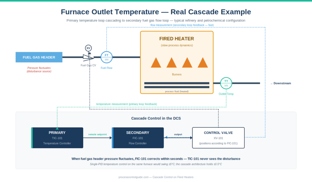
- Primary loop: Furnace outlet temperature transmitter → temperature controller → output drives secondary setpoint
- Secondary loop: Fuel gas flow transmitter → flow controller → output drives fuel gas control valve
The fuel gas header pressure was shared with multiple furnaces, so pressure fluctuations were constant. Without cascade, the temperature would have swung with every pressure change. With cascade, the fuel gas flow controller absorbed the pressure-induced disturbances within seconds, and the temperature held tight.
Reactor temperature cascade.
On a chemical reactor with steam-jacketed cooling, the cascade was:
- Primary loop: Reactor bulk temperature → temperature controller → output drives secondary setpoint
- Secondary loop: Cooling water flow → flow controller → output drives cooling water control valve
The cooling water supply pressure varied during the day as plant-wide demand changed. The secondary flow controller maintained constant cooling water flow regardless of supply pressure changes, keeping reactor temperature steady.
Compressor anti-surge cascade.
On a large oil and gas mega-project in Asia where I currently work, centrifugal compressors are protected by cascade-configured anti-surge controllers:
- Primary loop: Compressor operating point distance from surge line → anti-surge controller → output drives secondary setpoint
- Secondary loop: Recycle valve position → position controller → output drives recycle valve actuator
The position control loop ensures the recycle valve moves precisely as commanded, despite varying upstream pressure and valve nonlinearity. The anti-surge controller doesn’t have to compensate for valve characteristics — that’s the secondary’s job.
Distillation column reboiler cascade.
On a refining unit, distillation tray temperatures cascade to reboiler steam flow:
- Primary loop: Tray temperature → temperature controller → output drives secondary setpoint
- Secondary loop: Steam mass flow to reboiler → flow controller → output drives steam control valve
Steam header pressure varies with plant-wide demand. The cascade maintains steady heat input to the column despite header variations, producing tight tray temperature control and stable separation.
Cascade Control in DCS Platforms — Vendor Implementation Notes
All modern DCS platforms support cascade through standard function blocks. The configuration patterns differ slightly by vendor but the principles are identical.
Honeywell Experion PKS.
In Experion Control Builder, cascade is built using two PID function blocks. The primary PID’s output is connected to the secondary PID’s “SP” (setpoint) input via the cascade connection. Mode handling — Auto, Cascade, Manual — is built into the standard PID block. The secondary controller has a mode called “Cas” (cascade) that means “track the primary’s output as setpoint.”
On the oil and gas project in Asia I work on, cascade configurations are common across the BPCS. For deeper Experion context, see our Honeywell Experion PKS architecture guide.
Yokogawa CENTUM VP.
CENTUM uses two PID function blocks connected in cascade through the engineering tool. The terminology is “MASTER” and “SLAVE” rather than primary and secondary, but the concept is identical. CENTUM’s built-in cascade handling includes specific provisions for bumpless transfer when modes change. For deeper CENTUM context, see our Yokogawa CENTUM VP architecture guide.
Emerson DeltaV.
DeltaV’s PID function block has explicit “cascade” mode that simplifies the configuration. Two PID blocks are wired together and the secondary’s cascade mode automatically tracks the primary’s output. DeltaV’s documentation calls these “Outer Loop” and “Inner Loop” controllers. For deeper DeltaV context, see our Emerson DeltaV architecture guide.
The practical truth across vendors.
Configuring cascade is straightforward on every modern DCS. The engineering effort is in identifying which loops benefit from cascade, defining the intermediate variable measurement, sizing the secondary control element correctly, and tuning the loops in the right sequence. The actual function block wiring takes minutes; the engineering thought behind it takes longer. The ISA standards catalog publishes guidance documents on control architecture selection that complement vendor-specific implementation manuals.
Mode Transitions and Bumpless Transfer
One of the practical realities of cascade that textbooks rarely cover is mode transitions. Cascade loops can be in different operational modes:
- Primary in Manual, Secondary in Manual — both controllers in manual mode, operator directly controls the valve
- Primary in Manual, Secondary in Auto — operator manually sets the secondary setpoint, secondary tracks it
- Primary in Auto, Secondary in Cascade — normal operation, primary commands the secondary
- Primary in Cascade (in extended cascades with three or more loops)
Switching between these modes during operation is routine. An operator might switch a loop to manual to perform maintenance, then return it to cascade. A startup sequence might progress through several mode transitions before reaching normal operation.
The bumpless transfer requirement.
When a controller transitions modes, the controlled variable should not “bump” — meaning there should be no sudden jump in the valve position or process variable. Bumpless transfer requires the controller to initialize its internal state correctly during transitions.
Modern DCS platforms handle bumpless transfer automatically in standard PID blocks, but only if the configuration is correct. The classic failure mode is when an operator switches a cascade loop from manual back to cascade, and the secondary setpoint changes abruptly because the primary’s accumulated integral action was not properly initialized.
Configuration discipline for bumpless transfer.
- Use the vendor’s standard PID block with cascade support — don’t write custom logic that bypasses the built-in handling
- Enable initialization/tracking features that ensure the controller’s internal state matches the current operating point before transitions
- Test mode transitions during commissioning — don’t assume bumpless transfer works just because the function block claims it does
- Document operating procedures for mode transitions so operators understand the expected behavior
Common Cascade Mistakes I’ve Seen
After commissioning cascade loops on multiple oil and gas projects, here are the recurring mistakes:
Tuning the primary before the secondary. This is the most common mistake. The tuning order matters — secondary first, primary second. Reversing the order produces unstable, unreproducible tuning.
Cascading where there’s no benefit. Adding cascade complexity to a loop with no significant intermediate disturbances doesn’t improve control — it just adds tuning burden and potential failure modes.
Secondary loop not actually faster than primary. If the secondary’s natural response time is close to the primary’s, cascade provides no real benefit. The secondary needs to be substantially faster — at least 3-5x — for cascade to be worthwhile.
Forgetting to size the secondary final element correctly. If the secondary control valve is too small or too large for the duty, the secondary loop saturates frequently. A saturated secondary can’t do its job, and the cascade architecture provides no benefit during saturation.
Poor secondary measurement. Noisy, drifting, or unreliable secondary measurement causes the secondary controller to either chase noise or fail to track setpoint smoothly. The primary controller then sees an unstable inner loop and produces poor primary control.
Wrong tuning method on the secondary. Lambda tuning works well on most secondary loops because of its smooth setpoint tracking. Ziegler-Nichols-style aggressive tuning on a secondary loop produces oscillation that propagates to the primary.
Operator confusion about modes. Cascade introduces additional modes that operators may not understand. Without proper procedures and training, operators may inadvertently disable cascade or fail to return to cascade after maintenance.
Tuning the primary too aggressively. When the secondary loop is doing its job well, the primary’s “process” looks like a fast first-order lag. Engineers sometimes tune the primary as if the secondary doesn’t exist, applying aggressive gains that produce oscillation. The primary should be tuned for the combined system, not for the raw process.
Ignoring saturation handling. When the secondary saturates (valve at 0% or 100%), the primary loop has no way to influence the process. The primary controller continues to calculate output, but the secondary can’t respond. Anti-windup logic on the primary is essential to prevent integral action from accumulating during saturation periods.
Not testing mode transitions during commissioning. Bumpless transfer needs to be verified, not assumed. Walk through every mode transition with operations during commissioning to confirm the loops behave as expected.
Treating cascade as a magic solution. Cascade improves disturbance rejection on the secondary variable. It doesn’t fix fundamental process problems, oversized or undersized valves, sensor problems, or operator training issues. If a process has multiple problems, cascade addresses one specific category.
Frequently Asked Questions
What is cascade control in simple terms?
Cascade control is a control architecture where two PID controllers are connected in series. The output of an outer (primary) controller becomes the setpoint of an inner (secondary) controller. The primary controls the variable operations cares about; the secondary handles a faster intermediate variable. The combination provides better disturbance rejection than single-loop PID control.
What is the difference between cascade and feedback control?
Simple feedback control uses one PID loop to control one variable. Cascade uses two PID loops in series — a primary loop controls the important variable, and a secondary loop controls an intermediate variable that the primary’s output adjusts. Cascade is a form of feedback control, but with an inner loop that handles fast disturbances before they affect the primary variable.
Which loop do you tune first in cascade control?
Always tune the secondary (inner) loop first with the primary controller in manual mode. After the secondary tracks setpoint smoothly, switch to cascade mode and tune the primary. Reversing this sequence produces unstable, unreproducible tuning.
When should you use cascade control?
Use cascade when: (1) the process has significant disturbances on a measurable intermediate variable, (2) the intermediate variable responds substantially faster than the primary variable, (3) the final control element is nonlinear, or (4) the final control element has its own dynamics that interfere with primary control. Typical applications include furnace temperature, reactor temperature, compressor pressure, and distillation column control.
When should you NOT use cascade control?
Don’t use cascade when there’s no meaningful intermediate variable to measure, when the intermediate variable doesn’t respond faster than the primary, when the secondary loop would spend most of its time saturated, or when there are no significant disturbances to reject. Cascade adds complexity — use it when the benefit justifies the complexity.
What controllers are used in cascade control?
Both the primary and secondary controllers are typically PID (often actually PI without derivative action). The primary controller manages the slow primary variable like temperature or composition. The secondary controller manages a faster intermediate variable like flow, pressure, or valve position. Both controllers are configured using standard PID function blocks in modern DCS platforms.
Can you have multiple secondary loops in cascade?
Yes — extended cascade configurations with two or more secondary loops are possible. Each additional secondary loop adds tuning complexity. In practice, two-loop cascade (one primary, one secondary) is most common. Three-loop configurations occasionally appear in complex applications like compressor anti-surge with both position and flow secondaries.
What is bumpless transfer in cascade control?
Bumpless transfer means the controlled variable doesn’t jump when a cascade loop transitions between modes (manual ↔ auto ↔ cascade). Modern DCS platforms handle bumpless transfer automatically through standard PID block features, but configuration must be correct and the behavior should be verified during commissioning. Failed bumpless transfer creates sudden process upsets when modes change.
Is cascade control the same as feedforward control?
No. Cascade uses an inner feedback loop on a measurable intermediate variable. Feedforward control measures a disturbance directly and calculates a corrective action before the disturbance affects the process. Both improve disturbance rejection but through different mechanisms. The two can be combined — cascade plus feedforward — for difficult control problems.
Conclusion
Cascade control is one of the most useful advanced control techniques in process industries, found on essentially every refinery, gas plant, and petrochemical facility. The architecture is conceptually simple — two PID loops in series — but the engineering discipline matters: choosing where cascade helps, identifying the right intermediate variable, sizing the secondary loop correctly, tuning in the right sequence, and handling mode transitions cleanly.
The most important practical truths about cascade:
- Tune the secondary loop first, then the primary. Always.
- Cascade is a tool, not a default — use it when the problem fits, not as a universal solution.
- The secondary loop must be substantially faster than the primary for cascade to provide real benefit.
- Mode transitions and bumpless transfer need to be verified during commissioning, not assumed.
- Vendor implementation in modern DCS platforms is straightforward through standard function blocks; the engineering effort is in deciding what to cascade and how to tune it.
On every major project I’ve been part of, cascade loops outnumber single-feedback loops on the critical service applications. Furnace temperatures, reactor temperatures, compressor pressures, and column temperatures are almost universally controlled through cascade architectures. The economic value is real — better disturbance rejection translates directly to tighter product quality, less off-spec production, and lower energy waste.
If you’re new to cascade, start with simple two-loop configurations on processes that match the criteria above. Tune carefully, document mode behavior, and verify bumpless transfer. As you gain experience, the architecture becomes second nature and you’ll recognize which loops benefit from cascade and which don’t.
For broader process control theory context, see our PID Tuning Methods guide. For DCS platform context where these loops are configured, see our What Is a DCS cornerstone guide.
About the Author
Daniel Reed is an Instrument and Controls Engineer with 14+ years of oil and gas EPC experience across onshore and offshore projects in Asia and Africa. He currently works as a client-side I&C completion engineer on a large oil and gas mega-project in Asia, where he has been involved with Honeywell Experion PKS and Safety Manager since 2018.
His earlier work covered Yokogawa CENTUM and Triconex SIS on an offshore brownfield in Africa (2015-2018), and Yokogawa CENTUM and ProSafe-RS on a gas-to-liquids facility in Africa. His focus is engineering deliverable review, control and safety system commissioning, HAZOP/SIL/SIF participation, FAT/SAT execution, loop tuning across multiple DCS platforms, and vendor coordination across Honeywell, Yokogawa, Triconex, Allen-Bradley, and Siemens platforms.