I’ve worked with all three major safety instrumented system platforms in production environments. Triconex on an offshore brownfield in Africa from 2015 to 2018. Yokogawa ProSafe-RS on a gas-to-liquids facility in Africa earlier in my career. Honeywell Safety Manager on a large oil and gas mega-project in Asia from 2018 to today.
Cross-vendor SIS experience is genuinely rare, and most of what I know about safety systems comes from sitting in HAZOP sessions, validating cause-and-effect matrices, witnessing FAT and SAT, and walking down loops with operators during commissioning.
If you searched what is a safety instrumented system, you probably found articles that quote IEC 61511 at you without ever explaining what an SIS actually does on a real project. This guide takes a different approach.
I’ll walk through what an SIS is, why it must be architecturally separate from the DCS, what SIL ratings actually mean in practice, how HAZOP feeds into SIL assessment, and what differentiates the three major SIS platforms I’ve used. This is written from the field, not from the standard.
If you’re new to functional safety, this is the foundation. If you’ve been doing safety work for years, this might still be useful as a reference and a cross-vendor comparison.
TL;DR — Quick Answer: What Is a Safety Instrumented System?
A safety instrumented system (SIS) is a separate, certified, redundant control system that takes a process to a safe state when defined hazardous conditions are detected. It exists independently of the Distributed Control System (DCS) that handles normal process control, and it is governed by IEC 61511 — the process industry’s functional safety standard.
An SIS consists of three layers: sensors that detect hazardous conditions (pressure transmitters, temperature switches, gas detectors), a logic solver that executes interlock logic in deterministic real-time, and final elements that bring the process to safe state (shutdown valves, blowdown valves, motor trip relays).
The reliability of each safety function is quantified by a Safety Integrity Level (SIL 1 through SIL 4), determined through HAZOP and SIL assessment. The three platforms most commonly deployed in process industries are Schneider Triconex, Yokogawa ProSafe-RS, and Honeywell Safety Manager.
What You Will Learn
This guide answers what is a safety instrumented system comprehensively, covering:
- What an SIS does and why it’s different from a Basic Process Control System (BPCS)
- The three fundamental components: sensors, logic solver, final elements
- Why IEC 61511 requires architectural separation between DCS and SIS
- What SIL 1, SIL 2, SIL 3, and SIL 4 actually mean — and why SIL 4 rarely appears in process plants
- How HAZOP and LOPA feed into SIL assessment
- The IEC 61511 safety lifecycle from concept through decommissioning
- A first-person comparison of Triconex, ProSafe-RS, and Honeywell Safety Manager
- How cause-and-effect matrices are written, validated, and tested
- Common SIS mistakes I’ve seen on real projects
What Is a Safety Instrumented System
A safety instrumented system is exactly what its name suggests — a system, made of instruments, designed to take action when safety is at risk. But that simple definition hides what makes an SIS architecturally distinct.
To understand what is a safety instrumented system in working terms, you have to understand what it is not. An SIS is not a regular control system that happens to do safety. It is not “the safety part of the DCS.” It is not a glorified PLC with extra interlocks.
An SIS is a separate, certified, redundant system with its own controllers, its own I/O, its own engineering tools, and its own operator interfaces (or shared HMI access, depending on architecture). Its only purpose is to detect hazardous process conditions and take the process to a safe state — quickly, reliably, and independently of whatever the DCS is doing at that moment.
On every plant I’ve worked on, the SIS sits alongside the DCS but never inside it. The DCS controls the process during normal operation. The SIS waits. When defined safety limits are exceeded, the SIS acts — closes a shutdown valve, trips a feed pump, isolates a pressure vessel, dumps a reactor to safe state.
This separation matters because mixing safety and control in the same logic solver introduces failure modes that compromise both. IEC 61511 makes this separation a hard requirement, and every credible SIS architecture honors it.
The Three Fundamental Components of a Safety Instrumented System
Every safety instrumented system, regardless of vendor, is built from the same three component categories. Understanding these is foundational to understanding what is a safety instrumented system functionally.
Sensors (initiators).
Sensors detect when a process variable has moved outside safe limits. These are not just any process instruments — SIS sensors are typically certified to functional safety standards and selected for proof-test interval and failure mode analysis.
Common SIS sensors I’ve worked with include:
- Pressure transmitters with high/low SIL trip setpoints
- Temperature transmitters in critical thermowells
- Level transmitters (radar, displacer) on vessels with overfill or low-level hazards
- Flame and gas detectors for fire & gas systems
- Limit switches on valves for position confirmation
- Discrete devices like pressure switches and emergency stop pushbuttons
Logic Solver.
The logic solver is the brain of the SIS — the controller that executes interlock logic when sensor inputs indicate hazardous conditions. This is what people typically mean when they say “the SIS” — Triconex Tricon, ProSafe-RS controller, Honeywell Safety Manager.
Logic solvers run on certified, redundant architectures with diagnostic coverage that traditional PLCs don’t approach. Triple Modular Redundant (TMR) is the most common pattern, where three independent processors execute the same logic and outputs are voted before taking action. Certification bodies like TÜV Rheinland and TÜV SÜD audit and certify SIS logic solvers against IEC 61508 requirements.
Final Elements.
Final elements are what actually take the process to safe state. These are typically actuated shutdown valves (SDVs), blowdown valves (BDVs), motor trip contactors, or solenoid-operated emergency vents. Like sensors, final elements are selected and tested to specific functional safety requirements.
A safety function isn’t complete until you can trace it from sensor through logic solver to final element. That entire path is what carries the SIL rating — not the logic solver alone.
SIS vs BPCS — Why They Must Be Separate
The Basic Process Control System (BPCS) is what most engineers think of when they say “DCS” — the system that runs PID loops, manages alarms, handles sequences, and provides operator interfaces during normal operation. The safety instrumented system is a separate system that exists for one purpose: safe shutdown when something goes wrong.
IEC 61511 requires architectural separation between BPCS and SIS, and this requirement isn’t bureaucratic. It comes from operational experience and incident analysis.
The reasons for separation include:
- Independence from common-cause failure. If a single fault — software bug, network failure, power loss — could disable both control and safety simultaneously, you have no safety function. Separate systems with separate components avoid this.
- Different design integrity requirements. SIS components are selected and certified to higher reliability standards than BPCS components. Mixing them dilutes the integrity of the safety function.
- Different maintenance and testing. SIS components have proof-test intervals defined by their SIL rating. BPCS components don’t have these requirements. Combining them complicates compliance.
- Different change management. Changes to safety logic require formal management of change (MOC), SIL re-verification, and documented validation. Changes to BPCS don’t carry that overhead.
On the project I work on currently in Asia, the BPCS is Honeywell Experion PKS and the SIS is Honeywell Safety Manager. Even though they’re from the same vendor, they run on separate hardware, with separate engineering tools, separate change control, and separate validation requirements. Same vendor, separate systems.
For broader DCS context, see our What Is a DCS cornerstone guide.
IEC 61511 — The Standard That Governs Safety Instrumented Systems
IEC 61511 is the international standard that defines how a safety instrumented system must be designed, implemented, operated, and maintained in the process industries. It is the process industry’s interpretation of the broader IEC 61508 functional safety standard.
The standard covers:
- Safety lifecycle from concept through decommissioning
- Safety requirements specification
- SIS design and engineering
- SIL determination methodology
- Hardware fault tolerance requirements
- Software requirements for safety logic
- Verification and validation procedures
- Operation, maintenance, and modification
In North America, the equivalent standard is ANSI/ISA-84.00.01, which is technically harmonized with IEC 61511. OSHA in the United States recognizes IEC 61511 / ISA-84 as “recognized and generally accepted good engineering practice” for SIS design.
The IEC functional safety portal is the authoritative source for the current standard, and the ISA standards catalog is where to find the ISA-84 version.
In practice, IEC 61511 isn’t a book you read once and shelve. It defines the workflow that engineering teams follow on every safety project. HAZOP, SIL assessment, FAT, SAT, proof testing, MOC — all of these are lifecycle steps required by the standard.
SIL Ratings Explained — What SIL 1, 2, 3, and 4 Actually Mean
Safety Integrity Level (SIL) is a discrete rating from 1 to 4 that quantifies the required reliability of a safety function. It is not a rating of a product, a controller, or a sensor in isolation — it applies to the entire safety function from sensor through logic solver to final element.
SIL is measured by Probability of Failure on Demand (PFD) for low-demand systems, which is the typical mode in process industries. PFD is the probability that the safety function will fail to perform when called upon.
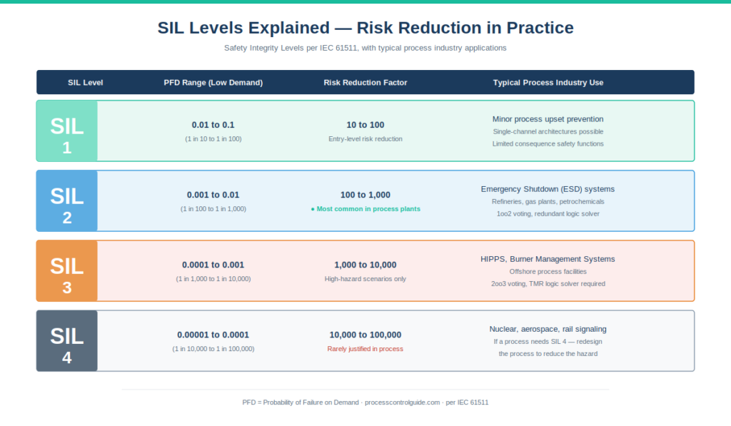
| SIL Level | PFD Range (Low Demand) | Risk Reduction Factor | Typical Application |
|---|---|---|---|
| SIL 1 | ≥ 10⁻² to < 10⁻¹ | 10 to 100 | Minor process upset prevention |
| SIL 2 | ≥ 10⁻³ to < 10⁻² | 100 to 1,000 | Most common in process plants |
| SIL 3 | ≥ 10⁻⁴ to < 10⁻³ | 1,000 to 10,000 | High-hazard processes, HIPPS |
| SIL 4 | ≥ 10⁻⁵ to < 10⁻⁴ | 10,000 to 100,000 | Rarely used in process; nuclear/aerospace |
SIL 1 is the entry level — covers safety functions where failure would lead to minor process upsets or limited consequences. Often achievable with single-channel architectures and standard certified components.
SIL 2 is the most common rating in process plant SIS applications. Most emergency shutdown functions on refineries, gas plants, and petrochemical facilities sit at SIL 2. Achievable with 1oo2 voting (one out of two — either sensor triggers shutdown) on sensors and redundant logic solvers.
SIL 3 is where engineering effort and cost increase substantially. Typical for high-hazard scenarios like Burner Management Systems (BMS), High Integrity Pressure Protection Systems (HIPPS), and offshore process facilities. Usually requires 2oo3 voting on sensors and triple-redundant logic solvers.
SIL 4 is technically defined in IEC 61511 but the standard itself notes it is not normally applied in the process industry. The engineering effort, cost, and validation burden to achieve SIL 4 are enormous. If your process needs SIL 4, the right answer is usually to redesign the process to reduce the hazard rather than engineer the SIS to that level.
On every project I’ve been part of, the vast majority of safety functions ended up at SIL 1 or SIL 2 after rigorous SIL assessment. A few SIL 3 functions appeared for specific high-hazard scenarios. I have never personally implemented a SIL 4 function in process industries.
For a deeper guide, see SIL Ratings Explained.
The Safety Lifecycle Per IEC 61511
IEC 61511 defines a complete safety lifecycle that runs from the earliest project concept through decommissioning, decades later. Understanding the lifecycle is essential to understanding what is a safety instrumented system as a project deliverable rather than just a piece of hardware.
The lifecycle phases I’ve personally participated in include:
- Hazard and Risk Assessment (HAZOP, LOPA). Identify what can go wrong, what protective layers exist, and what residual risk remains.
- Safety Requirements Specification (SRS). Document each safety function, its inputs, outputs, logic, response time, and SIL target.
- SIS Design and Engineering. Select sensors, logic solver, final elements; design redundancy; engineer cause-and-effect matrices.
- SIL Verification. Calculate achieved SIL from selected components and verify it meets the SRS target.
- Factory Acceptance Testing (FAT). Verify the system works in the vendor’s facility before shipping.
- Site Acceptance Testing (SAT). Verify the system works on site, integrated with field devices.
- Commissioning. Walk down every safety function, end-to-end, with operations.
- Operation and Maintenance. Proof testing per defined intervals, MOC for any changes.
- Modification. Any change requires impact assessment, SIL re-verification, re-validation.
- Decommissioning. Documented end-of-life with safety handover.
This isn’t a sequence you skip. Every phase has documentation deliverables that get reviewed, approved, and archived. On regulated industries (pharma, refining in some jurisdictions, offshore), regulatory audit checks these deliverables explicitly.
HAZOP, LOPA, and SIL Assessment
The starting point for any safety instrumented system is hazard identification. The standard workflow goes HAZOP → LOPA → SIL Assessment → SIS Design.
HAZOP (Hazard and Operability Study).
HAZOP is a structured, team-based review of process design that systematically identifies hazards. The team goes through every node of the process (a pump, a heat exchanger, a column) and applies guide words — “no flow,” “more pressure,” “less temperature,” “reverse flow” — to identify deviations from design intent and their consequences.
I’ve sat through HAZOP sessions that ran for weeks. They’re tedious but they catch hazards that no individual engineer would identify alone. The output is a HAZOP report listing every deviation, cause, consequence, existing safeguards, and recommended actions.
LOPA (Layer of Protection Analysis).
LOPA takes HAZOP findings and quantifies them. For each identified hazard scenario, LOPA assigns numerical values to the initiating event frequency, the consequences, and the existing protection layers (BPCS alarms, operator response, relief valves, mechanical protection).
If the residual risk after all existing layers exceeds the company’s tolerable risk threshold, additional risk reduction is required — typically a Safety Instrumented Function (SIF) with a specific SIL target.
SIL Verification.
SIL verification formalizes the LOPA output. For each safety function, the assessment determines the required SIL level based on the risk gap. This is what drives the SIS architecture — SIL 2 sensors require certain redundancy, SIL 3 sensors require more. Independent functional safety specialists such as exida publish certification data and failure rate libraries that engineering teams reference during verification.
The SIL assessment workshop is where representatives from operations, engineering, safety, and the SIS vendor sit together and agree on what each function must achieve. I’ve been part of many of these sessions, and the disciplined risk-based approach is genuinely impressive when done well.
For a deeper practitioner guide, see HAZOP and LOPA Explained.
The Three Major SIS Platforms — A Practitioner Comparison
I’ve worked with the three most widely deployed SIS platforms in process industries. Here’s the comparison based on direct experience.
| Aspect | Schneider Triconex | Yokogawa ProSafe-RS | Honeywell Safety Manager |
|---|---|---|---|
| Logic Solver Architecture | Triple Modular Redundant (TMR) | Dual or TMR variants | Quadruple Modular Redundant (QMR) options |
| SIL Certification | Up to SIL 3 | Up to SIL 3 | Up to SIL 3 |
| Native DCS Integration | Cross-vendor (mostly with Foxboro/Wonderware historically) | CENTUM VP (Yokogawa native) | Experion PKS (Honeywell native) |
| Engineering Tool | TriStation | SCS Manager | Safety Builder / Control Builder |
| My Project Experience | Offshore brownfield, Africa (2015-2018) | Gas-to-liquids, Africa (earlier) | Large oil and gas mega-project, Asia (2018-current) |
Schneider Triconex.
Triconex is the original TMR safety controller, with a long deployment history especially in offshore oil and gas. I worked with Triconex on an offshore brownfield in Africa where the existing SIS predated my involvement.
What I appreciated about Triconex was the maturity of the TMR architecture. The Tricon controllers I worked with had been running for years between scheduled outages. TriStation, the engineering tool, has its own learning curve but the underlying logic execution is rock-solid.
The trade-off with Triconex on multi-vendor projects is integration. When the DCS is Foxboro or Wonderware, integration is smooth. When the DCS is Honeywell or Yokogawa, it requires more engineering effort to coordinate cause-and-effect visibility on the HMI.
Yokogawa ProSafe-RS.
ProSafe-RS is Yokogawa’s SIS, and its strongest selling point is native integration with CENTUM VP. On the gas-to-liquids facility in Africa where I worked with both ProSafe-RS and CENTUM VP, the integration was as tight as you can get — same V-net/IP network, same HIS for operator visibility, same engineering environment workflow.
ProSafe-RS is engineered through SCS Manager, which is structured and conservative — characteristic of Yokogawa’s overall engineering culture. The discipline shows in regulated industries where validation overhead is significant.
For Yokogawa CENTUM VP architecture context including ProSafe-RS integration, see our Yokogawa CENTUM VP architecture guide.
Honeywell Safety Manager.
Safety Manager is what I work with daily on the oil and gas mega-project in Asia. Its strongest characteristic is native integration with Honeywell Experion PKS — same engineering tools at the front end (Control Builder), same HMI (Experion Station), same FTE network access.
Safety Manager runs on QMR (Quadruple Modular Redundant) architecture in its higher-tier configurations, which exceeds TMR in fault tolerance. SIL 3 certification is straightforward to achieve in the configurations Honeywell offers.
For Honeywell Experion PKS architecture context including Safety Manager integration, see our Honeywell Experion PKS architecture guide.
Honest comparison.
There’s no universally best SIS platform. Selection should follow installed base, DCS platform (native integration matters), regional engineering availability, and industry-specific requirements. All three platforms I’ve used carry SIL 3 certification and are mature enough for serious projects.
What matters more than vendor selection is the engineering discipline — the HAZOP rigor, the SIL assessment thoroughness, the cause-and-effect validation, the FAT/SAT execution. A well-engineered SIL 2 function on any of these platforms is safer than a poorly-engineered SIL 3 function on the same platform.
Cause and Effect Matrices — The Heart of SIS Logic
Cause and effect matrices (C&E matrices) are how SIS logic is documented and configured. They are explicit tables where rows represent causes (sensor inputs reaching trip setpoints) and columns represent effects (final element actions), with cells marking which causes trigger which effects under which conditions.
A typical safety function in a C&E matrix might read: “If pressure transmitter PT-101A or PT-101B reads above 150 barg (in 1oo2 voting), close shutdown valve XV-102 and trip feed pump P-301.” That single line represents a complete SIL-rated safety function.
The C&E matrix is a living document throughout a project. It is reviewed during HAZOP, refined during SIL assessment, validated during FAT, retested during SAT, walked down during commissioning, and updated through MOC during operation.
I’ve sat through countless cause-and-effect validation sessions. They are tedious — operations, engineering, safety, and vendor sitting together going through every row of every matrix, verifying logic, debating setpoints, confirming voting schemes. But they are non-negotiable. The C&E matrix is the source of truth for what the SIS actually does, and getting it wrong is how incidents happen.
Factory Acceptance Testing, Site Acceptance Testing, and Commissioning
Three distinct testing phases verify an SIS works as specified before it goes into operation.
Factory Acceptance Testing (FAT).
FAT happens in the vendor’s facility before the SIS ships to site. The system is built up on test benches with simulated I/O, and every safety function is tested against the cause-and-effect matrix. End-to-end logic, response times, alarm behavior, redundancy switchover — all verified before shipment.
A well-executed FAT for a large project runs multiple weeks. It catches issues that would otherwise be discovered on site at five to ten times the cost. I’ve never seen a major SIS project where shortening FAT didn’t cost more in commissioning rework.
Site Acceptance Testing (SAT).
SAT happens on site after the SIS is installed but before tie-in to field instruments. The system is verified to work in its actual deployed configuration with site power, cooling, and network.
Commissioning.
Commissioning is the most rigorous phase — the SIS is connected to actual field sensors and final elements, and every safety function is walked down end-to-end with operations. Pressure transmitters are simulated to trip setpoints, shutdown valves are observed closing, cause-and-effect behavior is verified against the design.
On the oil and gas project in Asia I’m currently on, safety instrumented system commissioning took months. Operations was involved at every step. Documentation was archived for regulatory audit. This is what functional safety actually looks like at scale.
Common SIS Mistakes I’ve Seen on Real Projects
After working with three safety instrumented system platforms across multiple major projects, here are the recurring mistakes:
Treating the SIS as a secondary task to DCS commissioning. SIS deserves its own engineering effort, validation, and commissioning sequence. Folding it into DCS commissioning as an afterthought consistently causes problems.
Underestimating cause-and-effect validation effort. A large project might have hundreds or thousands of C&E rows. Each row requires logic review, setpoint verification, voting confirmation, and end-to-end test. Budget time for this.
Skipping FAT to save schedule. This always costs more in commissioning rework. Sites are expensive; factories are cheap by comparison.
Mixing BPCS and SIS sensors on the same instruments. Some projects try to save money by sharing sensors between control and safety. IEC 61511 allows this in limited cases but it requires careful documentation and SIL verification. Done casually, it compromises both systems.
Assigning SIL 3 casually. SIL 3 carries significant engineering, hardware, and proof-testing burden. Default to SIL 2 unless the LOPA genuinely demands SIL 3. I’ve seen projects over-engineer safety functions to SIL 3 when SIL 2 would suffice — adding cost without adding actual safety.
Bypassing safety functions during commissioning. Sometimes necessary, but every bypass should be formally authorized, time-limited, and removed before final acceptance. Casual bypasses left in place are how incidents happen.
Failing to test failover. Redundant logic solvers are only redundant if you’ve verified failover works. Pull power from one redundancy half during commissioning. Don’t assume.
Ignoring proof-test scheduling. Every safety function has a proof-test interval defined by its SIL rating. Skipping proof tests because operations is busy isn’t a schedule decision — it’s a functional safety violation.
Treating MOC casually. Any change to SIS hardware, logic, or setpoints requires formal Management of Change with SIL re-verification. Casual “field changes” without MOC create unverified safety functions.
Frequently Asked Questions
What does SIS stand for?
SIS stands for Safety Instrumented System. It’s also sometimes called Emergency Shutdown System (ESD), Safety Shutdown System (SSS), or Safety Interlock System (SIL system, though this is imprecise). In IEC 61511 terminology, SIS is the preferred term.
What is the difference between BPCS and SIS?
BPCS (Basic Process Control System) is the DCS that handles normal process control — PID loops, sequencing, alarms, operator interface. SIS is a separate, certified system that takes the process to safe state when defined hazardous conditions occur. IEC 61511 requires architectural separation between BPCS and SIS to prevent common-cause failures.
What is a Safety Instrumented Function (SIF)?
A Safety Instrumented Function is a single safety action — for example, “close shutdown valve XV-102 if vessel pressure exceeds 150 barg.” Each SIF has its own SIL rating, its own sensors and final elements, and its own validation. An SIS is composed of multiple SIFs working together.
What SIL level is most common in process plants?
SIL 2 is the most common rating for emergency shutdown functions in refineries, petrochemical plants, and gas processing facilities. SIL 1 covers less critical functions; SIL 3 is reserved for high-hazard scenarios like HIPPS and burner management; SIL 4 is essentially never used in process industries.
What is a Safety Instrumented System example?
A common SIS example: a high-pressure reactor with three pressure transmitters (PT-A, PT-B, PT-C) feeding a logic solver in 2oo3 voting. If any two transmitters read above the trip setpoint, the logic solver closes feed valves, opens vent valves, and trips agitator motors — taking the reactor to safe state. This whole function is SIL 2 or SIL 3 depending on consequence severity.
How does IEC 61511 differ from IEC 61508?
IEC 61508 is the generic functional safety standard for electrical, electronic, and programmable electronic safety-related systems. IEC 61511 applies IEC 61508 specifically to the process industries (chemicals, oil and gas, refining, pharmaceuticals, pulp and paper). IEC 61511 is what process engineers use day-to-day.
Can the DCS perform safety functions?
A modern DCS has alarms and can take certain protective actions, but it cannot perform certified safety functions per IEC 61511. The standard requires that safety logic execute on a system architecturally separated from the BPCS. The DCS can complement safety (alarms give operators time to respond), but it cannot replace a certified SIS for SIL-rated functions.
Which SIS platform is best?
There is no universally best platform. Schneider Triconex, Yokogawa ProSafe-RS, and Honeywell Safety Manager are the three most widely deployed in process industries, and all three carry SIL 3 certification. Selection depends on the DCS platform (native integration matters), installed base, regional engineering availability, and industry fit.
How long does SIS commissioning take?
For a large oil and gas mega-project, SIS commissioning typically runs several months — extending after DCS commissioning is largely complete because SIS validation requires real field sensors and final elements operating. Smaller plants might commission an SIS in weeks. Walking down hundreds of cause-and-effect rows is time-intensive regardless of scale.
Conclusion
A safety instrumented system is the layer of protection that exists between a process running normally and a process that has lost control. It is not part of the DCS, even when both come from the same vendor. It is a separate, certified, redundant system governed by IEC 61511 with its own design integrity requirements, its own lifecycle, and its own engineering discipline.
The three platforms I’ve worked with — Schneider Triconex on the offshore brownfield in Africa, Yokogawa ProSafe-RS on the gas-to-liquids facility in Africa, and Honeywell Safety Manager on the oil and gas mega-project in Asia — each have their own engineering personalities and integration strengths. None is universally best. What matters more than vendor selection is the engineering rigor applied at every lifecycle phase.
If you are working on a safety instrumented system project, understanding what is a safety instrumented system architecturally is the foundation. Understanding the IEC 61511 lifecycle is the framework. Understanding SIL ratings is the integrity target. And understanding cause-and-effect matrices is the practical heart of safety logic.
The work is tedious. HAZOP sessions run for weeks. SIL assessments require disciplined risk-based thinking. FAT and SAT consume months. Commissioning walks down hundreds of safety functions one at a time. None of this is glamorous. All of it is non-negotiable.
For broader DCS context, see the What Is a DCS cornerstone guide. For specific vendor platforms that integrate with the three SIS systems discussed here, see our Honeywell Experion PKS architecture guide and Yokogawa CENTUM VP architecture guide.
For the broader architectural context — how the SIS fits within an industrial control architecture alongside DCS, PLC, and SCADA, including the standard hybrid pattern where SIS integrates tightly with the DCS while remaining architecturally independent — see our DCS vs SCADA vs PLC capstone guide.
About the Author
Daniel Reed is an Instrument and Controls Engineer with 14+ years of oil and gas EPC experience across onshore and offshore projects in Asia and Africa. He currently works as a client-side I&C completion engineer on a large oil and gas mega-project in Asia, where he has been involved with Honeywell Experion PKS and Safety Manager since 2018.
His earlier work covered Yokogawa CENTUM and Triconex SIS on an offshore brownfield in Africa (2015-2018), and Yokogawa CENTUM and ProSafe-RS on a gas-to-liquids facility in Africa. His focus is engineering deliverable review, control and safety system commissioning, HAZOP/SIL/SIF participation, FAT/SAT execution, and vendor coordination across Honeywell, Yokogawa, Triconex, Allen-Bradley, and Siemens platforms.