I’ve sat through more SIL assessment workshops than I can count. Operations, engineering, safety, and the SIS vendor in the same room for days, working through every safety function in a HAZOP report, debating setpoints, arguing about voting schemes, and ultimately deciding what SIL ratings each function needs to carry.
If you’re new to functional safety, SIL levels sound abstract. SIL 2, SIL 3, probability of failure on demand, risk reduction factor — the terminology is dense enough that most online explanations fall into two camps: dry textbook definitions of IEC 61511, or oversimplified one-liners that miss the actual engineering decisions.
This guide takes a different approach. I’ll walk through what SIL levels actually mean in practice, what drives the decision between SIL 2 and SIL 3 in a real assessment workshop, how voting architectures map to each level, and what mistakes I’ve seen on real projects.
If you’ve read our Safety Instrumented System guide, this article goes one level deeper on the SIL ratings question specifically.
TL;DR — Quick Answer: What Are SIL Ratings?
SIL ratings (Safety Integrity Levels) are discrete numerical ratings from 1 to 4 that quantify the required reliability of a safety function in a safety instrumented system. SIL 1 is the lowest level of risk reduction; SIL 4 is the highest. Each level corresponds to a specific Probability of Failure on Demand (PFD) range and a Risk Reduction Factor (RRF).
SIL ratings are defined by IEC 61508 and applied to process industries through IEC 61511. The rating applies to the entire safety function — sensor, logic solver, and final element working together — not to individual components in isolation. SIL 2 is the most common rating for emergency shutdown functions in process plants; SIL 3 is reserved for high-hazard scenarios; SIL 4 is essentially never used in process industries.
A safety function’s SIL level is determined through HAZOP, LOPA, and SIL assessment workshops — not assigned arbitrarily. Higher SIL ratings require greater hardware redundancy, stricter component certification, more disciplined proof-testing, and more rigorous documentation.
What You Will Learn
This guide covers SIL ratings in working-engineer detail:
- What each SIL level means in terms of probability and risk reduction
- The difference between SIL 1, SIL 2, SIL 3, and SIL 4 in real applications
- Why SIL ratings apply to safety functions, not individual products
- How HAZOP and LOPA feed into SIL assessment
- Hardware architecture requirements at each level (1oo2, 2oo3 voting)
- PFD calculations and Risk Reduction Factor
- The honest cost-benefit of SIL 2 versus SIL 3
- SIL verification and the math behind achieved SIL
- Common SIL rating mistakes from real projects
What Are SIL Ratings — A Definition That Means Something
A SIL rating is not a product attribute. It is not a hardware specification. It is a target reliability assigned to a Safety Instrumented Function (SIF).
To understand what SIL levels actually mean, you have to start with the safety function itself. A safety function is one specific protective action — for example, “close shutdown valve XV-102 if pressure transmitter PT-101 reads above 150 barg.” That whole chain — sensor through logic solver through final element — is the safety function, and the SIL rating applies to the chain.
When someone says “this is a SIL 3 transmitter,” they mean the transmitter is certified to support SIL 3 functions when integrated appropriately. The transmitter alone doesn’t have a SIL rating in functional terms. The complete safety function does.
SIL levels come from IEC 61508, the generic functional safety standard, and are applied to process industries through IEC 61511. The IEC functional safety portal is the authoritative source for these standards. In North America, the equivalent ISA-84 standard from the ISA standards catalog carries the same SIL framework.
In practice, These levels are how a project formally answers the question: “How reliable does this safety function need to be?” The answer drives hardware selection, redundancy architecture, proof-test intervals, validation requirements, and ongoing maintenance commitments for the life of the plant.
The Four SIL Levels — What Each One Actually Means
There are four SIL levels in IEC 61511, distinguished by Probability of Failure on Demand (PFD) and Risk Reduction Factor (RRF):
| SIL Level | PFD (Low Demand) | Risk Reduction Factor | Reliability |
|---|---|---|---|
| SIL 1 | 0.01 to 0.1 | 10 to 100 | 90% to 99% |
| SIL 2 | 0.001 to 0.01 | 100 to 1,000 | 99% to 99.9% |
| SIL 3 | 0.0001 to 0.001 | 1,000 to 10,000 | 99.9% to 99.99% |
| SIL 4 | 0.00001 to 0.0001 | 10,000 to 100,000 | 99.99% to 99.999% |
SIL 1.
SIL 1 covers safety functions where failure would result in minor process upsets or limited consequences. The required reliability — better than 90 percent of the time on demand — is achievable with single-channel architectures using standard certified components.
Examples from real projects include high-level alarms on non-critical tanks, low-pressure trips on auxiliary systems, and trip functions where the consequence of failure is operational rather than safety-critical.
SIL 2.
SIL 2 is the workhorse rating for emergency shutdown systems in process industries. The vast majority of emergency shutdown (ESD) functions on refineries, gas plants, petrochemical complexes, and LNG facilities sit at SIL 2. The required reliability — better than 99 percent on demand — is achievable with 1oo2 voting on sensors and a redundant logic solver.
Typical SIL 2 functions include vessel high-pressure trips, compressor anti-surge shutdowns, pump cavitation protection, furnace flame-out shutdowns, and most process-level ESD interlocks.
SIL 3.
SIL 3 is where engineering effort, cost, and certification burden escalate substantially. The required reliability — better than 99.9 percent on demand — typically requires 2oo3 voting on sensors, TMR (Triple Modular Redundant) logic solvers, and certified SIL 3-capable final elements throughout the safety function.
SIL 3 applications I’ve encountered include High Integrity Pressure Protection Systems (HIPPS) on subsea pipelines, Burner Management Systems (BMS) on large fired heaters and furnaces, and certain offshore process functions where consequence severity demands the higher integrity.
SIL 4.
SIL 4 is defined in IEC 61511 but the standard itself notes it is not typically applied in the process industry. The required reliability — better than 99.99 percent on demand — pushes engineering complexity, validation rigor, and proof-testing overhead to levels that almost always exceed what process risk reduction can practically achieve.
If a process genuinely needs SIL 4 to be tolerable, the right engineering response is usually to redesign the process to reduce the hazard. I have never personally implemented a SIL 4 safety function in a process plant. SIL 4 appears in nuclear power, rail signaling, and certain aerospace applications — domains with different risk frameworks than process industries.
How SIL Levels Are Determined — The Real Process
A safety function’s SIL level is determined through a structured risk assessment process. It is not assigned by intuition, vendor recommendation, or copying from a previous project. The process is HAZOP → LOPA → SIL Assessment.
HAZOP (Hazard and Operability Study).
HAZOP is a team-based review that systematically identifies hazards in a process design. The team works through every node — pumps, vessels, heat exchangers, compressors, columns — applying guide words like “no flow,” “more pressure,” “less temperature,” “reverse flow,” and “as well as.” For each deviation, the team identifies causes, consequences, existing safeguards, and recommended actions.
HAZOP doesn’t assign SIL ratings directly. It produces a list of hazard scenarios that may require additional protective layers. I’ve sat through HAZOP sessions that ran for multiple weeks on large projects. The discipline is tedious but it catches hazards that no individual engineer would identify alone.
LOPA (Layer of Protection Analysis).
LOPA takes HAZOP findings and quantifies them. For each hazard scenario, LOPA assigns numerical values to the initiating event frequency, the consequence severity, and the credit taken for each existing protection layer — BPCS alarms, operator response, mechanical relief, and so on.
The output of LOPA is a target Risk Reduction Factor for any new safety function required to close the residual risk gap. That target RRF maps directly to a SIL rating per the standard.
SIL Assessment Workshop.
The SIL assessment workshop is where the LOPA output gets formalized into specific SIL ratings for each Safety Instrumented Function. Representatives from operations, engineering, safety, and the SIS vendor sit together and work through every function.
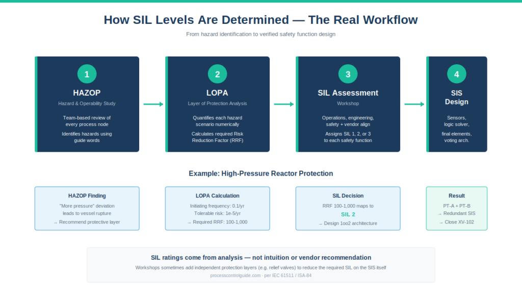
This is the room where the real decisions happen. The question isn’t just “what’s the calculated RRF” — it’s “given the calculated RRF, what’s the most practical SIL implementation we can engineer and maintain?” Sometimes the answer is to add additional protection layers (like a relief valve) so the SIS only needs SIL 2 instead of SIL 3. Sometimes it’s to accept higher SIL with the associated cost.
Independent functional safety specialists such as exida publish certification data and component failure rate libraries that engineering teams reference during these assessments.
SIL 2 vs SIL 3 — The Decision Most Engineers Face
Of all the SIL level decisions in a typical project, SIL 2 versus SIL 3 is the most consequential one engineers actually face in workshops. SIL 1 is usually obvious in either direction. SIL 4 is essentially excluded. The SIL 2/SIL 3 boundary is where the real engineering trade-offs live.
The reliability difference.
A SIL 3 function is 10 times more reliable than a SIL 2 function. SIL 2 fails at most once per 100 demands; SIL 3 fails at most once per 1,000 demands. That order-of-magnitude difference sounds small in abstract terms — but in cost and engineering effort, it’s enormous.
The hardware difference.
SIL 2 typically requires 1oo2 voting on sensors — two redundant sensors, either of which triggers the safety function. Logic solver redundancy is required but TMR is usually not. Final elements need to be SIL 2 capable but the certification overhead is manageable.
SIL 3 typically requires 2oo3 voting — three redundant sensors with majority voting before the safety function trips. TMR logic solvers become essentially mandatory. Final elements need higher certification levels with more rigorous failure rate documentation.
The cost difference.
Across the safety function — sensors, logic solver capacity, final elements, certification documentation, ongoing proof testing — SIL 3 typically costs 2 to 4 times more than SIL 2 for the equivalent function. On a large project with hundreds of safety functions, defaulting to SIL 3 instead of SIL 2 can add millions to project cost without commensurate safety benefit.
When SIL 3 is genuinely required.
SIL 3 is justified when LOPA analysis genuinely shows the residual risk after all other protection layers requires that level of reliability. Common scenarios include:
- HIPPS on subsea pipelines where pipeline rupture has catastrophic environmental and safety consequences
- BMS on fired equipment where uncontrolled fuel-air mixtures create explosion hazards
- Offshore facility ESD where evacuation difficulty amplifies consequence severity
- Certain toxic release scenarios in chemical plants
When SIL 3 is over-engineered.
I’ve sat in workshops where SIL 3 was proposed for functions that LOPA actually supported at SIL 2. The reasons varied — risk aversion, vendor pressure, “let’s add margin,” or simply not wanting to revisit the question. Defaulting to higher SIL ratings without LOPA justification adds cost without adding actual safety benefit.
The disciplined answer is: implement what the LOPA supports. Add an independent protection layer if needed to reduce required SIL. Don’t pay for SIL 3 reliability you don’t need.
Hardware Architecture by SIL Level — Voting Schemes Explained
The voting architecture of an SIS — how multiple redundant components combine to make a trip decision — is one of the most direct mappings between SIL levels and physical hardware.
1oo1 (One out of One).
Single channel. One sensor, one logic solver path, one final element. Cheapest architecture but offers no fault tolerance — any single failure can prevent the safety function from working. Suitable for SIL 1 in many cases; rarely sufficient for SIL 2 or higher.
1oo2 (One out of Two).
Two redundant sensors. Either sensor reading above the trip setpoint triggers the safety function. Provides fault tolerance against undetected failure of one sensor — if one fails silently, the other still trips. Common architecture for SIL 2 applications.
The trade-off with 1oo2 is spurious trip frequency. Either sensor failing high (false alarm) causes an unnecessary shutdown. On critical processes where spurious trips cost significant production, 1oo2 may not be the right choice.
2oo2 (Two out of Two).
Two sensors, both must read above trip setpoint to trigger. Reduces spurious trip frequency but reduces fault tolerance — if one sensor fails low (silent failure), the safety function won’t trip when it should. Not commonly used for safety-critical functions because of this failure mode.
2oo3 (Two out of Three).
Three sensors with majority voting — any two of three above setpoint triggers the safety function. Provides both fault tolerance and spurious trip resistance. The architecture of choice for SIL 3 applications.
2oo3 voting requires more hardware, more wiring, more terminations, more I/O channels, more diagnostics. On a brownfield retrofit, adding a third transmitter to existing dual-redundant instrumentation is a non-trivial mechanical and electrical effort.
TMR (Triple Modular Redundant) Logic Solver.
For the logic solver itself, TMR means three independent processors execute the same safety logic and outputs are voted before taking action. If one processor disagrees with the other two, the disagreeing path is isolated and the function continues on the remaining two. Triconex pioneered TMR logic solvers, and TMR is the typical architecture for SIL 3 SIS deployments. Certification of TMR logic solvers is typically performed by bodies such as TÜV Rheinland against IEC 61508 requirements.
For more on the three major SIS platforms and how they implement these architectures, see our Safety Instrumented System guide.
PFD, RRF, and the Math Behind SIL Ratings
The SIL rating system is grounded in two related quantitative metrics: Probability of Failure on Demand (PFD) and Risk Reduction Factor (RRF).
Probability of Failure on Demand.
PFD is the probability that a safety function will fail to perform its intended action when called upon. It’s a probability — a number between 0 and 1 (or between 0 percent and 100 percent if expressed that way).
PFD applies specifically to “low demand mode” safety functions — the typical mode in process industries, where the safety function is called upon less than once per year on average. High demand mode (more than once per year) uses a different metric called Probability of Failure per Hour.
The PFD calculation.
For a simplified single-channel safety function, PFD is calculated as:
PFD = (λDU × T) ÷ 2
Where λDU is the dangerous undetected failure rate per hour, and T is the proof-test interval in hours. The “÷ 2” accounts for the fact that on average a failure occurs at the midpoint of the test interval.
In practice, calculating PFD for a complete safety function involves contributions from all components — sensors, logic solver, final elements — plus considerations for common-cause failure between redundant channels. SIS vendors and certification bodies publish detailed failure rate libraries that engineering teams use during SIL verification.
Risk Reduction Factor.
RRF is simply the inverse of PFD: RRF = 1 ÷ PFD.
If a safety function has PFD = 0.001, its RRF = 1,000. That means the function reduces the risk of the underlying hazard by a factor of 1,000.
The SIL ratings map directly to RRF ranges:
- SIL 1 → RRF 10 to 100
- SIL 2 → RRF 100 to 1,000
- SIL 3 → RRF 1,000 to 10,000
- SIL 4 → RRF 10,000 to 100,000
Engineers tend to think in RRF terms because it’s intuitive — “this function reduces risk by 1000x.” Standards tend to express things in PFD terms because PFD is what the math actually calculates.
SIL Verification — Calculating Achieved SIL
There’s a distinction between target SIL and achieved SIL that matters in real projects.
Target SIL is what the LOPA says you need. “This function must achieve SIL 2 or better.”
Achieved SIL is what your engineered solution actually delivers. It’s calculated from the failure rates of the components you’ve selected, the voting architecture, the proof-test interval, and the diagnostic coverage.
SIL verification is the engineering activity that confirms achieved SIL meets or exceeds target SIL. This is usually done with specialized software — exSILentia from exida is one widely used tool, but several alternatives exist. The verification produces a documented calculation showing each safety function meets its target.
I’ve seen projects where target SIL was specified but verification was skipped. Six months into operation, someone realized the actual achieved SIL was lower than required because the selected final element wasn’t certified for the specified architecture. That kind of discovery during operation is expensive and embarrassing. Do the verification during design.
The Honest Cost of Higher SIL Ratings
There’s a tendency in some engineering organizations to default to higher SIL levels on the assumption that “more safety is always better.” This isn’t quite right, and on large projects the cost difference matters.
Hardware costs.
SIL 2 to SIL 3 typically increases hardware cost 2 to 4 times for the equivalent function. More sensors, redundant logic solver paths, higher-certified final elements.
Engineering costs.
SIL 3 requires more detailed failure mode analysis, more rigorous documentation, formal SIL verification with calculation backup, and dedicated functional safety management throughout the project lifecycle. Engineering hours increase substantially.
Operating costs.
SIL 3 components require more frequent proof testing than SIL 2 (typically 6 to 12 months versus 12 to 24 months). Each proof test takes operations time and risks the spurious trips that proof-testing sometimes triggers. Higher SIL means more ongoing operating burden.
Maintenance complexity.
More components mean more things to maintain, more spare parts to stock, more documentation to keep current. SIL 3 systems are not just more expensive to build — they’re more expensive to keep running for the life of the plant.
The honest engineering approach.
Use SIL levels the standard defines: implement what LOPA shows is needed, no more. If a SIL 3 target seems too high, look at whether independent protection layers can reduce the risk gap. A well-designed mechanical relief valve plus a SIL 2 SIS is often more cost-effective than a SIL 3 SIS alone — and may be safer because mechanical protection doesn’t share failure modes with electronic systems.
For vendor-specific context on how each major SIS platform handles SIL 3 certification, see our Honeywell Experion PKS architecture guide (Safety Manager) and Yokogawa CENTUM VP architecture guide (ProSafe-RS).
Common SIL Assessment Mistakes I’ve Seen
After participating in many SIL assessment workshops across multiple projects, here are the recurring mistakes:
Assigning SIL by intuition rather than LOPA. Sometimes a function “feels” like SIL 3 because the consequence sounds severe — but LOPA actually shows SIL 2 closes the risk gap. Do the formal analysis. Don’t assign SIL ratings by gut feel.
Confusing component SIL capability with function SIL. A SIL 3-capable transmitter is not the same as a SIL 3 safety function. The function rating depends on the complete chain including architecture, diagnostics, and final element. Component certification is necessary but not sufficient.
Skipping SIL verification during design. Target SIL gets specified in the SRS; verification gets deferred to “later.” Later sometimes never happens, or happens after the system is already installed and changes are expensive. Verify during design.
Adding “margin” by upgrading SIL levels. SIL 3 because “we want extra safety margin” instead of SIL 2 based on LOPA is not engineering — it’s risk aversion masquerading as engineering. It adds cost without commensurate benefit.
Ignoring spurious trip rate. A SIL 3 safety function with frequent spurious trips creates operating problems that may reduce overall plant safety because operators start bypassing or working around the system. Spurious trip frequency is a real engineering consideration alongside SIL rating.
Treating proof-test interval as optional. Each SIL level comes with an implied or specified proof-test interval. Stretching that interval to fit operations schedule isn’t a scheduling decision — it changes the achieved SIL. Document any deviation and accept the consequences.
Missing the human factor. SIL levels quantify equipment reliability. They don’t quantify operator response, maintenance discipline, or organizational safety culture. A SIL 2 function on a well-run plant can be safer than a SIL 3 function on a plant with poor safety culture. SIL levels are necessary but never sufficient for actual safety.
Documentation drift. SIL levels, target PFD, achieved PFD, hardware architecture, proof-test intervals — all need to stay current as the plant changes. MOC (Management of Change) must include SIL impact assessment for any change to SIS hardware, logic, or setpoints. Drift between documented and actual SIL is how achievement gaps creep in over time.
Frequently Asked Questions
What does SIL stand for?
SIL stands for Safety Integrity Level. It is defined by IEC 61508 as a discrete level (one of four) for specifying the safety integrity requirements of safety functions allocated to safety-related systems. In process industries, SIL ratings are applied through IEC 61511.
What is the highest SIL rating?
SIL 4 is the highest rating defined in IEC 61508. However, SIL 4 is essentially never used in process industries — the engineering complexity and cost are not practical at that level. SIL 3 is the highest commonly applied rating in process plant SIS.
What is the most common SIL rating in process plants?
SIL 2 is the most common rating for emergency shutdown functions in refineries, gas plants, petrochemicals, and LNG facilities. SIL 1 covers less critical functions; SIL 3 is reserved for high-hazard scenarios like HIPPS and BMS.
Are SIL ratings the same as PL ratings?
No. SIL (Safety Integrity Level) per IEC 61508 / 61511 is used in process and general industrial safety. PL (Performance Level) per ISO 13849 is used in machinery safety. The frameworks are related but distinct. Process SIS designs use SIL ratings.
Can a SIL 3 transmitter make a function SIL 3?
No. SIL ratings apply to the complete safety function — sensor, logic solver, and final element together — not individual components. Using a SIL 3-capable transmitter is necessary but not sufficient. The achieved SIL depends on architecture, diagnostic coverage, and the entire chain.
What’s the difference between SIL 2 and SIL 3?
A SIL 3 function is 10 times more reliable than SIL 2 (PFD of 0.0001-0.001 versus 0.001-0.01). Practically, SIL 3 typically requires 2oo3 voting versus 1oo2 for SIL 2, TMR logic solvers, higher-certified final elements, and more frequent proof testing. Cost is typically 2 to 4 times higher.
How are SIL ratings determined?
Through HAZOP (hazard identification), followed by LOPA (Layer of Protection Analysis) which quantifies required risk reduction, followed by SIL assessment workshops that formalize each safety function’s required SIL. These ratings are not assigned arbitrarily — they’re derived from documented risk analysis.
What is PFD in SIL ratings?
PFD is Probability of Failure on Demand — the probability that a safety function fails to perform its intended action when called upon. PFD is the primary metric defining each SIL level in low-demand mode (typical for process industries). Lower PFD means higher reliability and higher SIL.
Do SIL ratings require certification?
Components used in SIL-rated safety functions need to be certified by recognized bodies (TÜV Rheinland, TÜV SÜD, exida) to support the required SIL level. The complete safety function does not get a single certificate — instead, achieved SIL is verified through documented calculation using certified component data.
Conclusion
SIL ratings are the practical mechanism by which process industries express required safety function reliability. They’re not magic numbers, they’re not vendor specifications, and they’re not assigned by intuition. They emerge from disciplined risk analysis — HAZOP, LOPA, SIL assessment — and they drive concrete engineering decisions about sensors, logic solver architecture, voting schemes, final elements, and ongoing proof testing.
The most important practical truth about these ratings is that higher isn’t always better. SIL 3 costs significantly more than SIL 2 in hardware, engineering, and operating burden. The disciplined engineering answer is to implement what LOPA supports, not what feels safer in the moment. If a target seems too high, look at adding independent protection layers rather than over-engineering the SIS itself.
On every project I’ve worked on, the vast majority of safety functions land at SIL 1 or SIL 2 after rigorous assessment. A few SIL 3 functions appear for genuinely high-hazard scenarios. SIL 4 essentially never appears in process plants — when it would be needed, process redesign is the right answer.
If you’re new to SIL levels, the framework will feel abstract until you’ve sat through an actual SIL assessment workshop. Once you’ve watched the team work through real safety functions, debating voting schemes, weighing cost against reliability, and ultimately settling on the rating each function needs, the system makes sense.
For broader context on safety instrumented systems, see the Safety Instrumented System cornerstone guide. For the role of SIS in overall DCS architecture, see the What Is a DCS cornerstone guide.
About the Author
Daniel Reed is an Instrument and Controls Engineer with 14+ years of oil and gas EPC experience across onshore and offshore projects in Asia and Africa. He currently works as a client-side I&C completion engineer on a large oil and gas mega-project in Asia, where he has been involved with Honeywell Experion PKS and Safety Manager since 2018.
His earlier work covered Yokogawa CENTUM and Triconex SIS on an offshore brownfield in Africa (2015-2018), and Yokogawa CENTUM and ProSafe-RS on a gas-to-liquids facility in Africa. His focus is engineering deliverable review, control and safety system commissioning, HAZOP/SIL/SIF participation, FAT/SAT execution, and vendor coordination across Honeywell, Yokogawa, Triconex, Allen-Bradley, and Siemens platforms.