The first ratio control loop I commissioned was an air-to-fuel ratio controller on a fired heater on a gas-to-liquids facility in Africa. The fuel gas flow varied with the heater duty demand from the cascade above it, and the combustion air flow had to track the fuel gas flow proportionally — too much air wastes energy heating excess oxygen up the stack, too little air produces incomplete combustion, soot, and CO emissions.
The implementation looked simple on paper: measure fuel flow, multiply by a stoichiometric ratio, send the result as setpoint to the combustion air flow controller. But during commissioning, we tripped the heater twice because of a subtle failure mode the design hadn’t accounted for.
The fuel flow signal lagged the actual fuel delivery by a few seconds. When the cascade above stepped fuel demand up quickly, the air flow controller didn’t see the increased fuel demand until after the fuel was already burning fuel-rich. Brief excess fuel triggered the combustion analyzer’s low-O2 trip.
The fix was cross-limiting ratio — a safer architecture that ensures fuel never leads air on increasing demand and air never leads fuel on decreasing demand. It’s a small architectural change that prevents the dangerous combustion conditions cross-limiting is specifically designed to address. Most introductory content on this topic doesn’t even mention this, even though every industrial burner system uses it.
This guide walks through ratio from a working DCS commissioning engineer’s perspective. I’ll cover what ratio is, the wild stream concept, basic and cross-limiting architectures, real applications in combustion and blending, vendor implementation specifics, and common mistakes from real projects.
If you’ve read our Cascade Control Explained guide and Feedforward Control Explained guide, this article completes the foundational advanced regulatory control trio. It is structurally a form of feedforward, and it often combines with cascade for complete control strategies.
TL;DR — Quick Answer: What Is Ratio Control?
Ratio control is a control strategy that maintains a fixed proportional relationship between two process variables — typically two flow rates. One flow is the “wild stream” (measured but not controlled), and the other is the “controlled stream” (manipulated to maintain the desired ratio with the wild stream). The wild stream flow is multiplied by a ratio target to generate the setpoint for the controlled stream flow controller.
Common applications include air-to-fuel ratio in combustion (boilers, fired heaters, furnaces), reactant ratios in chemical reactors, blending ratios in mixing operations, reflux ratios in distillation columns, and chlorine-to-water ratios in water treatment.
Basic ratio uses a simple multiplier function block. Safety-critical applications like combustion use cross-limiting ratio control, which ensures the air-to-fuel relationship stays safe during transitions — fuel cannot lead air on increasing demand, and air cannot lead fuel on decreasing demand. This prevents the brief fuel-rich or fuel-lean conditions that can cause combustion safety issues.
Implementation in modern DCS platforms — Honeywell Experion PKS, Yokogawa CENTUM VP, Emerson DeltaV — uses standard ratio function blocks. The engineering effort goes into selecting the right wild stream measurement, calibrating the ratio target, designing safe transitions, and integrating the architecture with the overall plant control strategy.
What You Will Learn
This guide covers the topic at working-engineer depth:
- What ratio is and the wild stream concept
- Why ratio is structurally a form of feedforward
- Basic ratio architecture using multiplier blocks
- Cross-limiting ratio for combustion safety
- When ratio is the right answer
- When ratio is wrong or over-engineered
- Real ratio examples from combustion, blending, and distillation
- How ratio is implemented in Experion, CENTUM, and DeltaV
- Common ratio mistakes I’ve seen on real projects
What Is Ratio Control — A Working Definition
Ratio control is a control strategy that maintains a constant proportional relationship between two process variables. The classic implementation involves two flow streams: one whose flow is determined by external factors (the wild stream), and one whose flow is manipulated to maintain a fixed ratio with the wild stream (the controlled stream).
The basic equation is straightforward:
Controlled flow setpoint = Ratio target × Wild stream flow
When the wild stream flow changes, the controlled stream setpoint changes proportionally and the controlled stream flow controller adjusts its valve to track the new setpoint. The ratio target is typically operator-adjustable to allow for changes in operating conditions or recipe requirements.
Ratio control is one of the oldest forms of automatic control. The carburetor invented around 1890 was essentially a mechanical ratio device, mixing air and fuel in a defined proportion for combustion engines. These architectures became widespread in the 1950s and 1960s as pneumatic and then electronic instrumentation made flow measurement and proportional adjustment reliable enough for production use.
For technical depth on these architectures, ControlGuru provides practitioner-oriented references, and academic-level treatment with detailed mathematical analysis appears in recent journal publications such as the ScienceDirect article on this topic by Skogestad et al., which covers dual ratio and split-range variations.
The Wild Stream Concept — Why Terminology Matters
The wild stream and controlled stream terminology is essential to understand correctly. Mixing these up creates implementation problems that can be subtle and dangerous.
The wild stream is the flow that is measured but not controlled by the ratio system itself. It’s “wild” because it follows its own dynamics — set by an operator, controlled by an upstream system, or simply determined by process conditions. In a combustion application, the fuel gas flow is typically the wild stream because it’s commanded by the temperature cascade above. In a chemical blending application, the master ingredient flow set by production rate is the wild stream.
The controlled stream is the flow that the system manipulates to maintain the desired ratio. The ratio block multiplies the measured wild stream by the ratio target to generate the controlled stream’s setpoint. In combustion, the combustion air flow is typically the controlled stream that tracks fuel. In blending, the minor ingredients are typically controlled streams that track the master ingredient.
Why the terminology matters:
- If you reverse the assignment — making the safety-critical or rate-limited stream the “controlled” one when it should be the “wild” one — you can create transient conditions where the ratio is briefly wrong in dangerous directions
- The wild stream typically responds faster to operator commands (because it’s directly commanded); the controlled stream has additional dynamics from the ratio calculation and its own flow loop
- Sensor failure modes differ between wild and controlled streams. If the wild stream measurement fails, the ratio calculation produces wrong setpoints. If the controlled stream measurement fails, the controlled flow loop can’t track its setpoint accurately
Choosing which stream is wild and which is controlled is not arbitrary — it depends on the physics of the process, the safety considerations, and what’s being directly commanded by upstream control or operator action.
Why Ratio Control Matters in Process Plants
It matters because many industrial processes have a fundamental proportional relationship between two variables that must be maintained for the process to work correctly. Get the ratio wrong and you can get poor product quality, wasted energy, incomplete reactions, equipment damage, or safety incidents.
The business consequences of these failures include:
- Combustion efficiency losses — incorrect air-to-fuel ratio wastes fuel, generates excess emissions, and damages refractory linings
- Combustion safety incidents — fuel-rich combustion can produce uncombusted fuel that explodes when it reaches air; fuel-lean combustion can cause flame instability or flame-out
- Product quality variations — incorrect blending ratios produce off-spec product that must be reblended or sold at lower value
- Reaction yield losses — incorrect reactant ratios in chemical reactors produce side products or incomplete reactions
- Environmental compliance — incorrect chlorine-to-water ratios in water treatment cause regulatory violations
- Distillation column instability — incorrect reflux ratios disrupt column separation and product purity
On every refining, gas processing, and petrochemical facility I’ve worked on, ratio architectures are deployed extensively. Combustion control on every fired heater and boiler uses ratio architectures. Blending operations on product blenders use these architectures. Reactor feed systems use ratio. The cumulative economic value is significant — billions of dollars of product and millions of tonnes of CO₂ are managed through these architectures every year.
For broader DCS context where these loops live, see our What Is a DCS cornerstone guide.
Ratio Control Is Structurally Feedforward — An Important Insight
One conceptual point that’s worth understanding clearly: ratio is a form of feedforward. The wild stream measurement is functionally equivalent to a disturbance variable measurement in feedforward, and the ratio multiplication is the simplest possible form of feedforward calculation.
This insight matters for two reasons:
First, it means the same engineering principles apply. The wild stream measurement needs to be accurate (just like the disturbance measurement in feedforward). The ratio target needs to reflect the actual process relationship (just like the feedforward gain). Dynamic compensation may be needed if the wild stream dynamics differ from the controlled stream dynamics (just like in dynamic feedforward).
Second, it explains why ratio combines so naturally with cascade and feedback. Ratio is the feedforward component; cascade absorbs disturbances on the controlled flow’s intermediate variable; feedback PID trims residual error. The combination — ratio plus cascade plus feedback — is the standard architecture for serious combustion control and blending applications.
For deeper feedforward context, see our Feedforward Control Explained guide.
Basic Ratio Control Architecture
The simplest ratio architecture uses a multiplier function block to calculate the controlled stream setpoint from the wild stream measurement.
The basic structure:
- Wild stream flow transmitter — measures the wild stream flow continuously
- Ratio target — operator-adjustable parameter representing the desired ratio of controlled to wild flow
- Multiplier block — calculates: controlled stream SP = ratio × wild stream measurement
- Controlled stream flow controller — standard PID loop that drives the controlled stream’s control valve to track the calculated setpoint
- Controlled stream flow transmitter — measures the controlled stream flow for feedback to the PID
When the wild stream flow changes, the multiplier instantaneously generates a new setpoint for the controlled stream flow controller. The controlled stream’s PID then adjusts its valve to track the new setpoint. The ratio is maintained within the response time of the controlled stream PID.
Operator adjustment of the ratio.
In production, operators routinely adjust the ratio target to compensate for changing conditions. On a combustion application, the air-to-fuel ratio might be adjusted based on flue gas oxygen analyzer readings — more excess air during cold weather when fuel composition changes, less excess air when fuel quality is stable. On a blending application, ratio adjustments compensate for ingredient composition changes detected by quality analyzers.
The proportion is typically presented to operators as a single number representing the desired proportion. Behind the scenes, the DCS may apply scaling and engineering unit conversions, but the operator interaction stays simple.
Cross-Limiting Ratio Control — The Combustion Safety Architecture
Basic ratio has a subtle failure mode in combustion that cross-limiting is specifically designed to prevent. This is the architectural insight that distinguishes safe combustion control from unsafe combustion control, and it’s one of the most important practical concepts in industrial process control.
The problem with basic ratio on combustion:
Consider a fired heater where fuel demand increases rapidly (cascade above stepping up). With basic ratio:
- Fuel flow controller receives increased setpoint immediately
- Fuel valve opens to deliver increased fuel
- Wild stream measurement (fuel flow) shows the increased fuel
- Air ratio block calculates new air setpoint
- Air flow controller receives increased setpoint
- Air valve opens to deliver increased air
But there are time lags in this sequence. The fuel measurement, ratio calculation, air controller response, and air valve actuation each contribute milliseconds to seconds of delay. During those delays, fuel is already burning at the higher rate while the air is still catching up. The combustion is briefly fuel-rich — producing unburned hydrocarbons, soot, and potentially explosive conditions if the fuel-air imbalance is severe.
The reverse problem occurs on decreasing fuel demand. Fuel decreases first, then air follows, briefly creating fuel-lean conditions that can cause flame instability.
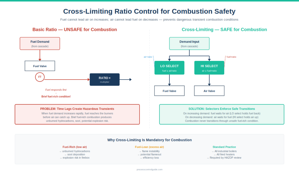
Cross-limiting structure:
Cross-limiting uses selector blocks to ensure fuel never leads air during increases and air never leads fuel during decreases. The architecture uses:
- HI selector on fuel demand: fuel setpoint = MAX(fuel command, lagged air measurement / ratio)
- LO selector on air demand: air setpoint = MAX(air command, lagged fuel measurement × ratio)
The result: on increasing demand, fuel flow is limited by the actual measured air flow (it cannot exceed the air’s capacity to support combustion). On decreasing demand, air flow is limited by the actual measured fuel flow (air cannot drop below what the fuel needs).
Combustion never goes fuel-rich during transitions because fuel is held back by the air measurement. Combustion never goes excessively fuel-lean because air is held back by the fuel measurement.
This architecture is the standard for combustion control on industrial boilers, fired heaters, and furnaces. API standards and combustion safety guidelines effectively require it. Implementing basic ratio on combustion without cross-limiting is a serious safety concern that should be raised during HAZOP review.
For broader safety context, see our Safety Instrumented System guide.
When to Use Ratio Control
It is the right answer when several specific conditions are met:
- The process has a fundamental proportional relationship between two variables that must be maintained
- One variable is measurable and rate-determining (the wild stream)
- The other variable can be manipulated to maintain the ratio (the controlled stream)
- The ratio relationship is stable enough to be characterized by a single ratio target (perhaps with periodic adjustment)
- The benefit of maintaining the ratio justifies the engineering effort
Typical applications in process industries:
- Air-to-fuel ratio on industrial boilers, fired heaters, and furnaces
- Reactant ratios in continuous chemical reactors
- Blending ratios in product blenders (gasoline blending, polymer blending, food blending)
- Reflux ratio in distillation columns
- Chlorine-to-water ratio in water treatment
- Acid-to-base ratio in pH control
- Steam-to-feed ratio in steam reformers
- Catalyst-to-feed ratio in catalytic processes
- Solvent-to-feed ratio in extraction operations
In each case, the underlying process has a stoichiometric, mass balance, or recipe-defined relationship between the two streams that the architecture maintains automatically.
When NOT to Use Ratio Control
This is the differentiator from much of the content online. Most articles present ratio as universally applicable. In practice, ratio is wrong for some applications.
Don’t use ratio when:
- There’s no fundamental proportional relationship between the variables — forcing a ratio where the process doesn’t have one creates problems
- The relationship is highly nonlinear or varies significantly with operating conditions — a single ratio target won’t capture the variation
- One of the streams isn’t reliably measurable — bad measurement means bad ratio calculations
- The wild stream has significant measurement noise — the noise gets multiplied through the ratio calculation
- The dynamics of the two streams are very different — the controlled stream may not be able to track the wild stream changes quickly enough
- The relationship is better expressed as a complex function rather than a simple ratio
- Combustion safety requires cross-limiting, but the operations team isn’t trained to recognize and respond to combustion alarms
Cases where I’ve seen ratio misapplied:
A blending application where the master ingredient flow had significant measurement noise — the ratio calculation amplified the noise and the controlled ingredients hunted constantly. Better: filter the master measurement appropriately or apply a different control strategy.
A reactor feed system where the desired ratio varied significantly with reaction temperature — a single ratio target was wrong most of the time. Better: ratio scheduling based on temperature, or model predictive control.
A combustion application where basic ratio was implemented without cross-limiting — the system worked at steady state but tripped during load changes. The fix was upgrading to cross-limiting architecture.
The honest engineering answer: ratio is one tool among several. Use it when the proportional relationship is genuine, the measurements are reliable, and the operations team understands the implementation.
Real Ratio Control Examples From Process Plants
Concrete examples illustrate where ratio is genuinely useful and how it’s implemented in practice.
Air-to-fuel ratio on a fired heater.
On the gas-to-liquids facility in Africa where I learned ratio architectures, the fired heater combustion architecture was:
- Cascade from outlet temperature to fuel gas flow (commanding fuel demand)
- Cross-limiting ratio from fuel gas measurement to combustion air setpoint
- Combustion air flow controller driving forced draft fan damper
- Flue gas oxygen analyzer providing trim correction to the ratio target
The combination held outlet temperature tight while maintaining safe combustion through all load changes. Excess oxygen ran at 2-3% during normal operation, with the trim correction adjusting the ratio target to maintain that target despite fuel composition variations.
Gasoline blending application.
On refining product blenders, multiple component streams are blended to produce finished gasoline grades. The architecture typically uses one component (often the alkylate or reformate) as the master stream with operator-set total flow, and the other components (butane, ethanol, additives) flowing at operator-set ratios to the master.
Quality analyzers on the blended product provide trim correction to the ratios. When the analyzer detects octane below target, the higher-octane component ratio increases. The blending continues continuously, with the ratios being adjusted slowly based on quality feedback.
Reflux ratio on distillation.
On distillation columns, reflux ratio is critical to separation. The architecture sets reflux flow as a ratio to the distillate product flow:
- Distillate flow is determined by overhead level control
- Reflux flow is calculated as ratio × distillate flow
- The ratio target is operator-adjustable based on column performance and product purity requirements
This architecture maintains constant reflux ratio regardless of column rate changes, which is important for separation efficiency.
Steam-to-feed ratio on a steam reformer.
On a steam reformer in the gas-to-liquids facility, the steam-to-carbon ratio in the reformer feed was critical to catalyst protection and product yield. The steam flow was ratio-controlled to the natural gas feed flow, with a minimum ratio enforced for safety (insufficient steam can cause catalyst coking).
The minimum ratio enforcement is critical — operators could adjust the ratio upward but not below the safe minimum. This was implemented through a HI selector that compared operator ratio setpoint to the safety minimum.
Ratio Control Implementation in DCS Platforms
All modern DCS platforms support these architectures through standard function blocks. The configuration patterns differ slightly by vendor but the principles are identical.
Honeywell Experion PKS.
In Experion Control Builder, ratio uses the RATIO function block or equivalent multiplier blocks. The block accepts the wild stream measurement input, a ratio parameter, and outputs the calculated setpoint. Cross-limiting requires additional HI and LO selector blocks wired in the standard configuration. On the oil and gas mega-project in Asia where I currently work, ratio configurations are used on every fired heater and boiler in the BPCS.
For deeper Experion context, see our Honeywell Experion PKS architecture guide.
Yokogawa CENTUM VP.
CENTUM provides a dedicated RATIO function block in the standard library. The block handles ratio calculation, operator interaction, and engineering unit scaling automatically. Cross-limiting is implemented using SS (Signal Selector) blocks in HI and LO modes. CENTUM’s structured approach makes these configurations straightforward to standardize across multiple loops. For deeper CENTUM context, see our Yokogawa CENTUM VP architecture guide.
Emerson DeltaV.
DeltaV implements ratio through standard arithmetic blocks combined with PID function blocks. The configuration is flexible — engineers can build basic ratio, cross-limiting ratio, or more complex variations using the standard function block library. DeltaV’s documentation provides reference configurations for common applications. For deeper DeltaV context, see our Emerson DeltaV architecture guide.
The practical truth across vendors.
Configuring these architectures is straightforward on every modern DCS. The engineering effort goes into selecting the right wild stream measurement, calibrating the ratio target through process testing, designing safe cross-limiting where needed, and documenting the configuration so operators understand it. The ISA standards catalog publishes guidance on these architectures that complements vendor-specific implementation manuals.
Common Ratio Control Mistakes I’ve Seen
After commissioning these configurations on multiple oil and gas projects, here are the recurring mistakes:
Implementing basic ratio without cross-limiting on combustion. This is the most serious mistake because it creates safety risk. Any combustion application — boiler, fired heater, furnace — needs cross-limiting. Basic ratio is acceptable for blending and non-safety applications but not for combustion.
Wrong assignment of wild and controlled streams. Putting the rate-limited or safety-critical stream as “controlled” when it should be “wild” creates transient hazards. Think carefully about which stream should command and which should follow.
Forgetting dynamic compensation. If the wild stream and controlled stream have significantly different response dynamics, the ratio gets temporarily wrong during transitions. Lead-lag dynamic compensation may be needed for safety-critical applications.
Amplifying measurement noise through the ratio calculation. A noisy wild stream measurement, multiplied through the ratio block, becomes a noisy controlled stream setpoint. Filter the wild stream measurement appropriately before using it.
Ratio target set incorrectly at commissioning. The ratio target should reflect actual process stoichiometry, calibrated through testing. Engineers sometimes use design values that don’t match reality. Verify it during commissioning and adjust if needed.
Forgetting safety minimums and maximums. Some applications need enforced limits on the ratio — minimum air-to-fuel ratio for combustion safety, minimum steam-to-carbon ratio for reformer protection. These should be enforced through HI/LO selector blocks, not just operator discipline.
Ignoring sensor failure modes. If the wild stream measurement fails (broken transmitter, signal loss), the ratio calculation produces garbage. The DCS configuration should handle this gracefully — fail to last-known-good value, fail-safe to minimum or maximum, or alarm and stop the ratio calculation.
Not training operators on the architecture. Operators need to understand which stream is wild, which is controlled, how the ratio target is adjusted, and what alarms indicate ratio problems. Without training, operators may inadvertently disrupt the ratio architecture or fail to respond correctly to alarms.
Combining ratio with cascade incorrectly. Ratio is often combined with cascade, but the integration requires careful thought. The ratio block’s output may need to feed the cascade’s remote setpoint, or the cascade’s output may need to feed the ratio’s calculation. Getting the structure wrong creates confusing control behavior.
Treating ratio as set-and-forget. Ratio targets need periodic review based on process performance. Combustion ratios drift with fuel composition changes; blending ratios drift with feedstock changes; reactor ratios drift with catalyst aging. Periodic loop performance review catches this drift.
Frequently Asked Questions
What is ratio control in simple terms?
Ratio control is a control strategy that maintains a fixed proportional relationship between two process variables. The flow of one stream (the wild stream) is measured and multiplied by a ratio target to generate the setpoint for a second flow (the controlled stream). When the wild stream changes, the controlled stream follows proportionally.
What is the wild stream in ratio control?
The wild stream is the flow that is measured but not directly controlled by the ratio system. It’s “wild” because it follows its own dynamics — perhaps set by an operator, controlled by an upstream system, or determined by process conditions. The system uses the wild stream measurement to calculate the setpoint for the controlled stream.
What is cross-limiting ratio control?
Cross-limiting ratio is a safety-enhanced architecture used in combustion control. It uses HI and LO selector blocks to ensure fuel never leads air during increasing demand and air never leads fuel during decreasing demand. This prevents brief fuel-rich or fuel-lean combustion conditions during transitions. Cross-limiting is the standard architecture for industrial boilers, fired heaters, and furnaces.
What is the difference between ratio and feedforward control?
Ratio is structurally a form of feedforward control — it uses a measurable variable (the wild stream) to calculate a corrective action (controlled stream setpoint) before any deviation occurs. The distinction is more about terminology than function: “ratio control” typically refers to maintaining a proportional flow relationship, while “feedforward” is the broader category including ratio and other architectures.
When should you use ratio control?
Use ratio when the process has a fundamental proportional relationship between two variables, one variable is rate-determining (wild stream), the other can be manipulated to follow (controlled stream), and the ratio is stable enough to be characterized by a single target. Typical applications include combustion, blending, reactant ratios, and reflux ratios.
Can ratio control be combined with cascade?
Yes — ratio plus cascade is a common combination. For example, on a fired heater: temperature cascade commands fuel flow, ratio commands air flow proportional to fuel, and the entire architecture provides tight temperature control with safe combustion. The combination requires careful integration but is widely used in industrial practice.
What is air-to-fuel ratio?
Air-to-fuel ratio maintains a stoichiometric proportion between combustion air and fuel in industrial boilers, fired heaters, and furnaces. The architecture is typically cross-limiting, ensuring safe combustion through all load transitions. The ratio target is often trimmed by flue gas oxygen analyzer feedback to maintain optimal excess oxygen.
What is reflux ratio on distillation?
Reflux ratio maintains the desired proportion of liquid reflux returning to the column versus distillate product leaving the column. It’s critical to distillation separation efficiency. The architecture typically sets reflux flow as a ratio of distillate flow, with the ratio target adjusted based on column performance and product purity requirements.
Is ratio control hard to tune?
The ratio target itself is set based on process stoichiometry, not tuned in the PID sense. The controlled stream PID is tuned like any flow controller — typically with Lambda tuning. The dynamic compensation (if any) and cross-limiting selectors need to be configured correctly but aren’t tuned in the traditional sense. Ratio is generally easier to implement than cascade or full feedforward.
Conclusion
Ratio control is one of the foundational advanced regulatory control techniques in process industries. It maintains proportional relationships between variables that are essential to combustion efficiency and safety, product quality in blending, reaction yields, and distillation performance. Implementation is straightforward in modern DCS platforms, but the engineering judgment in choosing the right wild stream, calibrating the ratio target, and applying cross-limiting where needed makes the difference between safe, robust control and dangerous or unreliable control.
The most important practical truths about ratio control:
- Ratio is structurally a form of feedforward — the wild stream measurement is functionally a disturbance variable
- Cross-limiting is mandatory for combustion applications — basic ratio is dangerous on burners
- The assignment of wild versus controlled streams is not arbitrary — it depends on process physics and safety
- Ratio targets need calibration during commissioning and periodic review during operation
- Ratio combines naturally with cascade for complete control strategies on fired heaters, reactors, and distillation columns
On every refining, gas processing, and petrochemical facility I’ve worked on, ratio architectures are deployed extensively. Combustion control on every fired heater and boiler uses ratio architectures. Blending operations on product blenders use ratio architectures. Reactor feed systems and steam reformers use the architecture with safety enforcement. The cumulative economic and safety value is substantial.
If you’re new to ratio architectures, start with simple blending applications where the consequences of getting it wrong are economic rather than safety-related. Build experience with the wild stream concept and ratio target calibration. As you gain experience, move to combustion applications with cross-limiting architectures, taking the safety considerations seriously throughout.
For broader process control theory context, see our PID Tuning Methods guide, Cascade Control Explained guide, and Feedforward Control Explained guide. For DCS platform context where these architectures are configured, see our What Is a DCS cornerstone guide.
About the Author
Daniel Reed is an Instrument and Controls Engineer with 14+ years of oil and gas EPC experience across onshore and offshore projects in Asia and Africa. He currently works as a client-side I&C completion engineer on a large oil and gas mega-project in Asia, where he has been involved with Honeywell Experion PKS and Safety Manager since 2018.
His earlier work covered Yokogawa CENTUM and Triconex SIS on an offshore brownfield in Africa (2015-2018), and Yokogawa CENTUM and ProSafe-RS on a gas-to-liquids facility in Africa. His focus is engineering deliverable review, control and safety system commissioning, HAZOP/SIL/SIF participation, FAT/SAT execution, loop tuning across multiple DCS platforms, and vendor coordination across Honeywell, Yokogawa, Triconex, Allen-Bradley, and Siemens platforms.