The moment I understood why ISA-101 matters wasn’t in a training session or a standards document. It was in the control room on the offshore brownfield in Africa around 2016, watching a senior operator respond to a process upset on a fifteen-year-old HMI design.
The screens were dense with information — gray backgrounds, every value displayed at maximum brightness, valve symbols in saturated reds and greens whether they were running normally or in alarm, dozens of numeric values competing for attention with no visual hierarchy.
When a critical alarm came in, the operator scanned the screen for what felt like ten seconds before he could find the abnormal variable. He found it eventually, took the right action, and the process recovered. But ten seconds is a long time in a process upset. That delay wasn’t an operator problem — it was a screen design problem. The HMI was actively working against him during the moment when it should have been helping most.
A few years later, on the gas-to-liquids project in Africa, I worked with a control room redesigned to the standard’s principles. Same operators, same process complexity, much faster response to abnormal situations. The difference wasn’t the people or the equipment — it was the HMI design philosophy that prioritized situational awareness over information density. That experience shaped how I think about HMI on every project since.
This guide is the practitioner explanation of ISA-101 I wish I’d had when I first encountered the standard. I’ll walk through what ISA-101 actually requires, why high-performance HMI changes operator response times measurably, how the information hierarchy works, and how the standard gets implemented on Honeywell Experion, Yokogawa CENTUM, and Emerson DeltaV.
If you’ve read our What Is a DCS cornerstone guide, this article goes deep on the HMI design discipline that determines whether the DCS actually helps operators do their job.
TL;DR — Quick Answer: What Is ISA-101?
ISA-101 (officially ANSI/ISA-101.01-2015, titled “Human Machine Interfaces for Process Automation Systems”) is the international standard that defines how operator HMI screens should be designed, implemented, operated, and maintained for industrial process automation systems. the standard covers the full HMI lifecycle from philosophy through retirement.
The standard exists because operator effectiveness depends critically on HMI design. Dense, cluttered, color-saturated screens slow operator response during abnormal situations. the standard establishes principles — situational awareness, consistent color usage, information hierarchy, navigation patterns, alarm display integration with ISA-18.2 — that produce HMIs proven to reduce operator response time and improve incident outcomes.
the standard applies across continuous, batch, and discrete process industries and is used to design HMIs for every major DCS platform (Honeywell Experion, Yokogawa CENTUM, Emerson DeltaV, ABB 800xA, Siemens PCS 7) as well as PLC-based SCADA systems (Wonderware, Ignition, iFIX, Citect).
Key concepts:
- High-Performance HMI — visually calm normal state, immediately recognizable abnormal conditions
- Color usage discipline — colors only mean something specific (status, not aesthetic choice)
- Information hierarchy — Level 1 (overview), Level 2 (unit), Level 3 (equipment), Level 4 (diagnostic) displays
- Situational awareness — operators see what they need without searching
- Alarm integration — works hand-in-hand with ISA-18.2 alarm management
- Lifecycle approach — design, implement, operate, maintain, modify
What You Will Learn
This guide covers ISA-101 at practitioner depth:
- What ISA-101 is, what it requires, and why it exists
- The five-phase HMI lifecycle defined by the standard
- The High-Performance HMI concept and why it works
- Color usage standards and what each color means
- The four-level information hierarchy (Level 1 through Level 4 displays)
- How the standard integrates with ISA-18.2 alarm management
- HMI philosophy, style guide, and toolkit — the three deliverables
- How the standard gets implemented on Honeywell Experion, Yokogawa CENTUM, and Emerson DeltaV
- Common implementation mistakes I’ve seen on real projects
- High-performance HMI vs traditional HMI — concrete differences from real migrations
What ISA-101 Is and Why It Exists
To understand ISA-101 properly, you have to understand what it replaced and why the change was necessary.
The HMI problem before the standard.
Before standardized HMI design principles, every DCS HMI was designed by whoever happened to be available — engineering teams, integrators, sometimes vendor consultants. The graphical conventions reflected whatever felt intuitive at the time, which often meant skeuomorphic representations of physical equipment (3D pump bodies, beveled vessel outlines, photorealistic instrumentation symbols).
Colors were chosen for aesthetic appeal rather than communication. Red was often a primary equipment color rather than a reserved alarm indicator. Backgrounds were dark or gray to look “industrial.” Every numeric value was displayed at full brightness because more visible meant more important. Animations were added because the technology made them possible.
The result was HMIs that looked sophisticated and were genuinely difficult to use during abnormal situations. The operator scanning experience I described in the opening — searching a dense screen for the abnormal variable — was the norm, not the exception, on plants commissioned through the 1990s and into the 2000s.
The research that drove standardization.
Through the late 1990s and 2000s, the Abnormal Situation Management Consortium (ASM Consortium), Center for Operator Performance, and various academic research groups studied how operators actually perceived and processed HMI information during abnormal situations. The findings were consistent and uncomfortable for the industry:
- Operator response time during abnormal situations was directly correlated with HMI design quality
- Dense graphics with no visual hierarchy slowed operator pattern recognition
- Color saturation across the normal display reduced the visibility of alarm colors
- Skeuomorphic equipment representations distracted from process variable values
- Inconsistent navigation across screens caused operators to lose context during upsets
This research, combined with operator effectiveness studies showing measurable productivity and safety improvements when HMIs followed high-performance principles, led to the development of this formal standard. ANSI/ISA-101.01 was published in 2015 after years of development through the ISA standards committee.
What ISA-101 actually requires.
The standard doesn’t prescribe specific screen designs — it establishes principles and a lifecycle framework. The standard requires that an organization develop and document:
- An HMI Philosophy — the guiding principles for ISA-101 HMI design at the facility
- An HMI Style Guide — specific design rules (colors, symbols, layouts, navigation)
- An HMI Toolkit — the reusable graphic objects implementing the style guide
- A defined lifecycle process — design, review, deploy, maintain, modify, retire
The principles within those documents must align with high-performance HMI concepts: situational awareness, consistent color usage, information hierarchy, integration with alarm management, and operator-centered design.
On the oil and gas mega-project in Asia where I currently work, the the lifecycle deliverables filled multiple binders and required several months of engineering effort just to establish the foundation before any graphics were built. That investment is what the standard expects — not a quick aesthetic refresh but a foundational design discipline.
For broader DCS context, see our What Is a DCS cornerstone guide.
The Five-Phase HMI Lifecycle
the standard takes a lifecycle approach similar to ISA-18.2 (alarm management) and IEC 61511 (functional safety). The standard defines five phases that every HMI program should follow:
Phase 1 — ISA-101 HMI Philosophy.
The philosophy document establishes the foundational principles for ISA-101 HMI design at the facility. It defines what high-performance HMI means in your context, what operator roles will use the HMI, what situational awareness goals are being pursued, and how HMI design supports operator effectiveness during normal and abnormal operations. The philosophy is created once and reviewed periodically; it sets the direction for everything that follows.
Phase 2 — HMI Design.
This phase produces the HMI Style Guide and HMI Toolkit. The Style Guide specifies exact design rules — color palette, symbol library, layout templates, navigation patterns, alarm display formats, typography. The Toolkit implements the Style Guide as reusable graphic objects (faceplates, symbols, templates) that ensure consistency across all screens.
Phase 3 — HMI Implementation.
Implementation is where the Style Guide and Toolkit are applied to build the actual operator graphics. On a large project, this is months of engineering effort — every process unit, every piece of equipment, every interlock screen needs to be built or migrated. Display testing and operator review happen during this phase.
Phase 4 — HMI Operation.
Once deployed, the HMI is used daily by operators. the standard expects feedback loops — operators identify screens that don’t work as expected, engineering teams adjust, the toolkit evolves. Operator effectiveness metrics (response time to alarms, time to resolve abnormal situations) feed back into HMI improvements.
Phase 5 — HMI Management of Change and Retirement.
Any change to the HMI — new equipment added, process modified, alarm philosophy updated — requires management of change with proper review and validation. Eventually screens are retired and replaced as the plant evolves or migrates to new control system platforms.
This lifecycle approach is what distinguishes the standard from a one-time HMI design effort. The standard expects continuous improvement over the 25-30 year life of the plant.
The High-Performance HMI Concept Explained
The core principle driving the standard is high-performance HMI. Understanding why this concept works requires understanding how operators perceive and process visual information.
The human perception problem.
The human brain processes large amounts of visual information in parallel, but it has limited capacity for focused attention. When operators monitor an HMI, peripheral vision continuously scans the entire screen for changes; focal vision examines specific information when something attracts attention. Both modes work together to support situational awareness.
This perception model has implications for HMI design that traditional design philosophy got wrong:
- Saturation reduces sensitivity. If everything is colored, nothing stands out. Abnormal conditions become harder to detect, not easier.
- Complexity slows pattern recognition. Dense graphics with many visual elements require focused attention to process, slowing the peripheral-vision scanning that detects anomalies.
- Motion attracts attention. Animations that aren’t communicating actionable information distract from real anomalies that are.
- Consistent layouts enable pattern matching. When operators have seen hundreds of similar screens, anomalies on familiar layouts are detected quickly. Inconsistent layouts break this pattern matching.
The high-performance HMI response.
High-performance HMI design responds to these realities by making the normal operating state visually calm and unobtrusive while making deviations immediately recognizable. The screen shouldn’t compete for attention during normal operation; it should make abnormal conditions impossible to miss.
Concrete design choices that implement this principle:
- Muted color palette for normal operation. Process flow diagrams use gray or pale colors, not saturated greens and blues. The screen looks deliberately calm.
- Bold color reserved for status changes. Yellow indicates warning conditions. Red indicates alarms or shutdowns. White or bright color indicates operator-selected information.
- Numeric values displayed by exception. Values within normal range are shown in muted form (or hidden entirely on overview displays). Values outside normal range become bold and colored.
- Skeuomorphic detail removed. Equipment is shown as functional schematic symbols, not 3D rendered pumps and vessels. The graphic communicates function, not photorealism.
- Animations limited to motion that communicates information. A spinning pump impeller animation doesn’t communicate anything useful and distracts from real alarms. It gets removed.
What changes for operators.
On the gas-to-liquids project where I first worked with a properly designed high-performance HMI, the difference was immediate. Operators could glance at a unit overview and instantly see if anything was abnormal — no scanning, no searching, no parsing. Abnormal conditions visually demanded attention; normal operation was visually unobtrusive.
Research from the ASM Consortium and Center for Operator Performance has documented response time improvements of 30-50% on properly designed high-performance HMIs compared to traditional screens. On a major refinery or petrochemical complex, that response time improvement translates directly to incident prevention and reduced downtime.
Color Usage Standards
Color usage is one of the most visible aspects of implementation. The standard establishes color discipline that differs sharply from traditional HMIs.
The color philosophy.
Colors should mean something specific. Every color on the screen should communicate a state or condition. Decorative color usage — making equipment “look like” its real-world counterpart, choosing colors for aesthetic appeal — is explicitly discouraged.
Typical color usage (varies by facility per HMI philosophy):
- Gray / muted tones — Normal operation, background elements, process lines, equipment outlines in normal state
- White / pale yellow — Operator-selected or recently-changed values that need temporary attention
- Yellow / amber — Warning conditions, deviations approaching alarm limits, advisory information
- Red — Alarm conditions requiring operator action, shutdown trips, critical safety indicators
- Blue — Diagnostic or maintenance information, sometimes used for cold/water systems where the convention is well-established
- Magenta / purple — Manual mode, operator override, bypass conditions
- Green — Use is controversial; the standard generally recommends against green for “normal” because it desensitizes operators. Some philosophies use green only for explicit confirmations (valve confirmed closed, motor confirmed running) but most use muted gray for normal states
What gets removed compared to traditional HMIs.
Traditional HMIs used color extensively:
- Pumps colored bright red or blue (because pumps physically look that way)
- Pipes colored to indicate fluid type (red for hot water, blue for cold, etc.)
- Vessels rendered with shaded 3D appearance
- Saturated background colors for visual interest
All of this disappears in implementation. The screen looks deliberately less interesting. Operators initially find this unfamiliar; within a few weeks, the calmer screen becomes preferred because abnormal conditions are dramatically more visible.
The Four-Level Information Hierarchy
the standard establishes an information hierarchy with four levels of operator displays, each serving a specific purpose. This hierarchy is one of the most practical contributions of the standard.
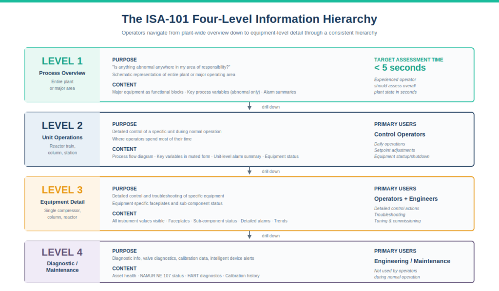
Level 1 — Process Overview.
The highest-level display showing the entire plant or major unit. Level 1 displays answer: “Is anything abnormal anywhere in my area of responsibility?” The graphic is intentionally schematic — major equipment shown as functional blocks, key process variables displayed only when abnormal, alarm summaries visible. An experienced operator should be able to assess overall plant state in under five seconds from a Level 1 display.
Level 2 — Unit / Area Operations.
The operating-level display for a specific unit or area (a reactor train, a distillation column, a compressor station). Level 2 displays show the detail an operator needs to control that unit during normal operation. Process flow is shown, key process variables are visible in muted form, alarms within the unit are summarized. This is where operators spend most of their time during normal operation.
Level 3 — Equipment Detail.
Drill-down displays showing detail for specific equipment — a single compressor, a single column, a single reactor. Level 3 displays support detailed control actions and troubleshooting. More numeric data is visible, equipment-specific faceplates are shown, sub-component status is displayed.
Level 4 — Diagnostic / Maintenance.
The deepest displays showing diagnostic information, maintenance status, valve diagnostics, instrument calibration data, intelligent device alerts. Level 4 displays are typically used by engineering staff or maintenance personnel rather than operators during normal operation.
Navigation between levels.
the standard expects consistent navigation patterns. From a Level 1 overview, clicking on a unit drills down to Level 2. From Level 2, clicking on equipment drills down to Level 3. The navigation hierarchy should be intuitive enough that operators don’t have to learn it explicitly — they just navigate based on what they want to see.
On the project I work on currently, this hierarchy was carefully designed during the the design phase. Operators move smoothly from plant-wide overview down to individual valve diagnostics without thinking about the navigation. The consistency makes the HMI a tool that supports operator effectiveness rather than an obstacle to it.
How HMI and Alarm Management Standards Integrate
The HMI standard and ISA-18.2 are companion standards. the standard governs how operators see information; ISA-18.2 governs which alarms exist and what priorities they have. The two work together — ISA-18.2 defines the alarm system; the HMI standard displays it effectively.
ISA-18.2 in brief.
ISA-18.2 (Alarm Management for the Process Industries) defines:
- Alarm philosophy and rationalization
- Alarm priorities (typically critical, high, medium, low or similar)
- Alarm flood thresholds (typically 10+ alarms/minute = flood condition)
- Response time expectations
- Performance metrics for the alarm system
For the complete practitioner treatment of ISA-18.2 — including the ten-stage alarm management lifecycle, the alarm philosophy document, the rationalization workshop process, alarm priorities with response times, performance targets, and implementation across major DCS platforms — see our ISA-18.2 Alarm Management guide.
the standard’s role in alarm display.
the standard governs how those rationalized alarms appear on operator screens:
- Color usage — alarm color (typically red) is reserved for actual alarm conditions, never for decorative use
- Alarm summary banners — consistent display of current alarms, prioritized, with acknowledge controls
- Embedded alarm indicators — alarm states visible in context on process graphics, not just in summary lists
- Alarm flood handling — display behavior during flood conditions to maintain operator situational awareness
Why integration matters.
An excellent alarm system designed to ISA-18.2 can still fail if the HMI displays alarms poorly. Conversely, an excellent HMI design to the standard can be undermined by an alarm system that floods operators with poorly rationalized alarms. The two standards must be implemented together for either to deliver its potential benefit.
On every project I’ve worked on, HMI and alarm management implementation happen in parallel. The HMI Style Guide specifies how alarms appear; the Alarm Philosophy specifies which alarms exist. Both teams work together throughout design and commissioning.
HMI Philosophy, Style Guide, and Toolkit — The Three Deliverables
the standard expects three specific documentation deliverables that together implement the standard at a facility.
The HMI Philosophy.
This is the foundational document — typically 20-50 pages — that establishes guiding principles. The philosophy answers strategic questions:
- What are the operator roles at this facility and what do they need from the HMI?
- What situational awareness goals does the HMI support?
- What color philosophy will be used?
- What information hierarchy will be implemented?
- How will alarms be displayed?
- How will HMI changes be managed?
- What operator effectiveness metrics will be tracked?
The philosophy is created once during the HMI program initiation and reviewed periodically. It provides direction without being prescriptive about specific design choices.
The HMI Style Guide.
The ISA-101 Style Guide translates the philosophy into specific design rules. Typically 100+ pages with extensive examples, the Style Guide specifies:
- Exact color palette with hex codes or RGB values
- Symbol library for valves, pumps, tanks, instruments
- Layout templates for each display level
- Navigation patterns and screen identifiers
- Faceplate designs for common equipment types
- Alarm display formats and priority indicators
- Typography rules (fonts, sizes, weights)
- Background colors and gridding
The Style Guide is the reference engineers consult when building or migrating any screen. It removes design judgment from individual engineers and centralizes it in the documented standard.
The HMI Toolkit.
The ISA-101 Toolkit is the implementation of the Style Guide as actual graphic objects in the DCS engineering environment. On Honeywell Experion, the Toolkit is a library of Experion graphic objects. On Yokogawa CENTUM, it’s a library of CENTUM graphic blocks. On DeltaV, it’s a library of DeltaV operator graphic objects.
The Toolkit lets engineering teams build new screens quickly because the standard symbols, faceplates, and templates are pre-built. Consistency is enforced because there’s only one way to draw a pump (the toolkit pump object), only one way to display a valve, only one alarm summary banner format.
On the project I work on currently, the Toolkit took several months to develop properly. Once it was complete, building new screens became fast and consistent. The upfront investment in the Toolkit paid back many times over during the bulk graphics work.
Implementation on Major DCS Platforms
Every major DCS platform supports implementation, though the specifics vary. Here’s the comparison from my experience across the three major platforms.
Honeywell Experion PKS.
Experion’s HMI environment (Experion Stations) supports full implementation. Modern Experion deployments build a custom toolkit of graphic objects that implement the facility’s HMI Style Guide. Honeywell offers reference aligned graphics libraries that can be customized.
Key Experion considerations:
- HMIWeb is the modern graphics technology in Experion
- Faceplates are implemented as Experion graphic objects with embedded logic
- Navigation hierarchy is built using Experion’s standard navigation tools
- Alarm summaries integrate with Experion’s native alarm subsystem
For broader Experion context, see our Honeywell Experion PKS architecture guide.
Yokogawa CENTUM VP.
CENTUM’s HIS (Human Interface Station) similarly supports implementation through customizable graphic libraries. Yokogawa offers reference graphics that can be customized to facility-specific requirements.
Key CENTUM considerations:
- Graphic Builder is CENTUM’s primary screen development tool
- Sub-graphic library supports reusable Toolkit objects
- Faceplate library is extensive and customizable
- Multi-window functionality on HIS supports Level 1/2/3 navigation patterns
For broader CENTUM context, see our Yokogawa CENTUM VP architecture guide.
Emerson DeltaV.
DeltaV Operate (the HMI) supports the standard through its graphic display tools and library system. Emerson offers DeltaV graphic libraries aligned with the standard’s principles.
Key DeltaV considerations:
- DeltaV Operate Run supports the runtime HMI environment
- Library Manager supports reusable Toolkit graphics
- Module faceplates can be configured per the standard
- Integration with batch (ISA-88) extends the design patterns to batch operations
For broader DeltaV context, see our Emerson DeltaV architecture guide.
ABB 800xA and Siemens PCS 7.
Both platforms support implementation similarly. ABB 800xA’s Process Portal and Siemens PCS 7’s WinCC OS environment both have graphic libraries and faceplate frameworks that accommodate the standard’s principles. Vendor-specific reference libraries are available.
Cross-platform reality.
Despite the different toolsets, the ISA-101 implementation approach is similar across platforms: develop the philosophy, write the style guide, build the toolkit in the vendor’s graphic environment, then implement screens using the toolkit. The vendor differences affect how the toolkit gets built, not the design principles being implemented.
For the broader architectural decision of which platform to use, see our DCS vs SCADA vs PLC capstone guide.
Common Implementation Mistakes I’ve Seen
After implementing the standard on multiple projects across multiple platforms, here are the recurring mistakes:
Skipping the HMI Philosophy and going straight to graphics. The philosophy feels theoretical when there are screens to build, but skipping it means design decisions get made ad hoc as graphics development progresses. Inconsistency creeps in. The Style Guide ends up reverse-engineered from whatever graphics happened to get built first. Always do the philosophy first.
Underestimating the Toolkit effort. Building a comprehensive Toolkit takes months on a large project. Engineering teams under schedule pressure often skip Toolkit development and build screens directly from raw vendor symbols. This produces inconsistent screens that violate the Style Guide and creates rework when violations are caught during review.
Treating the standard as an aesthetic refresh. Some projects approach it as “make the screens look modern.” The standard is fundamentally about operator effectiveness, not aesthetics. Changes that don’t measurably improve operator response time or situational awareness aren’t high-performance HMI improvements.
Ignoring operator input during design. Operators are the primary HMI users. the design must include operator input from philosophy through implementation. Designs that look great on paper but don’t match how operators actually work create friction during commissioning.
Failing to integrate with ISA-18.2. HMI design and alarm management are interdependent. Designing the HMI without coordinating with the alarm rationalization team produces an HMI that doesn’t display alarms effectively no matter how well it follows the graphic design principles.
Inconsistent navigation across screens. Even when individual screens follow the Style Guide, inconsistent navigation between screens defeats the purpose. Operators lose context when navigation patterns change. Navigation rules must be specified in the Style Guide and enforced during implementation.
Migrating old screens piecemeal. Some brownfield projects try to migrate one screen at a time over years. Operators end up with mixed environments — some screens high-performance, others legacy — which is more confusing than either pure approach. Migrate by complete operating unit, not by individual screen.
Forgetting management of change for HMI. Once high-performance screens are deployed, casual changes “to make this one screen look like the operator wants” violate the Style Guide and break consistency. HMI MOC must be formalized.
Not measuring operator effectiveness. the standard’s benefit is measurable — operator response time during abnormal situations, time to resolve upsets, alarm acknowledgment performance. Projects that don’t measure these miss the opportunity to demonstrate the standard’s value and identify areas for continuous improvement.
Treating the standard as one-time work. Plants evolve. New equipment is added. Processes change. HMI must evolve with them. the lifecycle approach expects ongoing maintenance, not one-time delivery.
Frequently Asked Questions
What is ISA-101?
ISA-101 (ANSI/ISA-101.01-2015) is the international standard for designing, implementing, operating, and maintaining Human-Machine Interfaces (HMIs) for process automation systems. It establishes principles for high-performance HMI design that improve operator situational awareness and response time during abnormal situations.
What does the standard require?
the standard requires three deliverables: an HMI Philosophy document establishing guiding principles, an HMI Style Guide specifying exact design rules, and an HMI Toolkit implementing the Style Guide as reusable graphic objects. The standard also defines a five-phase lifecycle: philosophy, design, implementation, operation, and management of change.
What is high-performance HMI?
High-performance HMI is the design philosophy that produces visually calm screens during normal operation while making abnormal conditions immediately recognizable. It reduces color saturation during normal states, displays numeric values by exception, removes skeuomorphic detail, and uses bold color only for status changes that demand operator attention.
What colors does the standard use?
the standard uses muted/gray tones for normal operation, yellow for warnings, red for alarms and shutdowns, magenta for manual mode and bypasses, and pale yellow/white for recently-changed or operator-selected values. Saturated colors are reserved for status indication, not decoration.
What is the four-level HMI hierarchy?
the standard defines four display levels: Level 1 (process overview — entire plant or major unit), Level 2 (unit/area operations — detailed operating displays), Level 3 (equipment detail — single equipment focus), and Level 4 (diagnostic/maintenance — engineering and maintenance information).
How does the HMI standard relate to ISA-18.2?
the standard governs how operators see information; ISA-18.2 governs which alarms exist and their priorities. The two standards must be implemented together — ISA-18.2 rationalizes the alarm system; the HMI standard displays those rationalized alarms effectively. Both are required for an effective operator interface.
Can I retrofit the standard to an existing HMI?
Yes, but it requires substantial engineering effort. Most HMI retrofits happen during DCS migrations (TDC3000 to Experion PKS, CENTUM CS3000 to CENTUM VP, etc.) when the HMI is being rebuilt anyway. Standalone HMI modernization projects on otherwise-stable DCS installations are less common but feasible.
How long does implementation take?
For a large oil and gas mega-project, implementation typically takes 6-18 months from philosophy through deployment, running in parallel with broader DCS engineering. Philosophy development alone is several weeks. Style Guide and Toolkit development can take several months. Bulk graphics work depends on plant size.
Which DCS platforms support the standard?
All major DCS platforms support it: Honeywell Experion PKS, Yokogawa CENTUM VP, Emerson DeltaV, ABB 800xA, Siemens PCS 7, and Rockwell PlantPAx. Each vendor provides reference aligned graphics libraries that can be customized to facility-specific HMI Style Guides.
Is ISA-101 mandatory?
ISA-101 is a voluntary consensus standard, not regulatory mandate in most jurisdictions. However, regulated industries (pharmaceuticals under FDA, certain oil and gas operations under OSHA Process Safety Management) increasingly reference ISA-101 as the recognized good engineering practice for HMI design. Compliance is typically expected for new facilities and major modifications.
Conclusion
ISA-101 is the foundation discipline that determines whether the DCS actually helps operators do their job or actively works against them during the moments when help matters most. The standard is fundamentally about operator effectiveness — not aesthetics, not modernization for its own sake, but the measurable difference in how quickly operators can detect abnormal conditions and respond appropriately.
The most important practical truths about ISA-101:
- High-performance HMI design changes operator response times measurably (typically 30-50% improvement on properly designed screens)
- The standard requires three deliverables — philosophy, style guide, toolkit — that together implement the design discipline
- The four-level information hierarchy (Level 1 overview through Level 4 diagnostic) creates intuitive navigation and effective situational awareness
- The HMI standard integrates with ISA-18.2 alarm management; both standards must be implemented together for either to deliver its benefit
- Implementation is a lifecycle commitment, not a one-time project
- Every major DCS platform supports the standard; the design principles transfer across vendors
On every project I’ve worked on with proper ISA-101 implementation, the operator experience is dramatically different from pre-standard environments. Operators detect abnormal conditions faster. Alarm response is more deliberate and effective. The cognitive load of monitoring a continuous process is genuinely lower. These improvements are observable in daily operations and measurable in incident response data.
If you’re approaching an HMI design or migration decision, the most important investment you can make is in the foundational deliverables — philosophy, style guide, toolkit — before any bulk graphics work begins. Skipping these to save schedule is the most common reason implementations fail to deliver their potential benefit. The discipline that the standard requires upfront pays back over the entire life of the plant.
For broader DCS context, see our What Is a DCS cornerstone guide. For platform-specific implementation context, see our Honeywell Experion PKS architecture guide, Yokogawa CENTUM VP architecture guide, and Emerson DeltaV architecture guide. For the broader architectural decision of where the HMI fits within an overall control system, see our DCS vs SCADA vs PLC capstone guide.
For the companion standard governing how the HMI layer connects to enterprise systems above it — including the Purdue Reference Model, the Level 3-4 interface, and how ISA-101 fits within the broader manufacturing integration framework — see our ISA-95 Enterprise Integration guide.
About the Author
Daniel Reed is an Instrument and Controls Engineer with 14+ years of oil and gas EPC experience across onshore and offshore projects in Asia and Africa. He currently works as a client-side I&C completion engineer on a large oil and gas mega-project in Asia, where he has been involved with Honeywell Experion PKS and Safety Manager since 2018.
His earlier work covered Yokogawa CENTUM and Triconex SIS on an offshore brownfield in Africa (2015-2018), and Yokogawa CENTUM and ProSafe-RS on a gas-to-liquids facility in Africa. His focus is engineering deliverable review, control and safety system commissioning, HAZOP/SIL/SIF participation, FAT/SAT execution, HMI design to industry standards across multiple DCS platforms, and vendor coordination across Honeywell, Yokogawa, Triconex, Allen-Bradley, and Siemens platforms.